


Page 34
Heat & Glo • NorthStar EPA Fireplace • 480-1081C
September 1, 2008
September 1, 2008
September 1, 2008
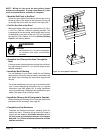
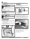
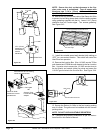
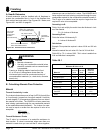
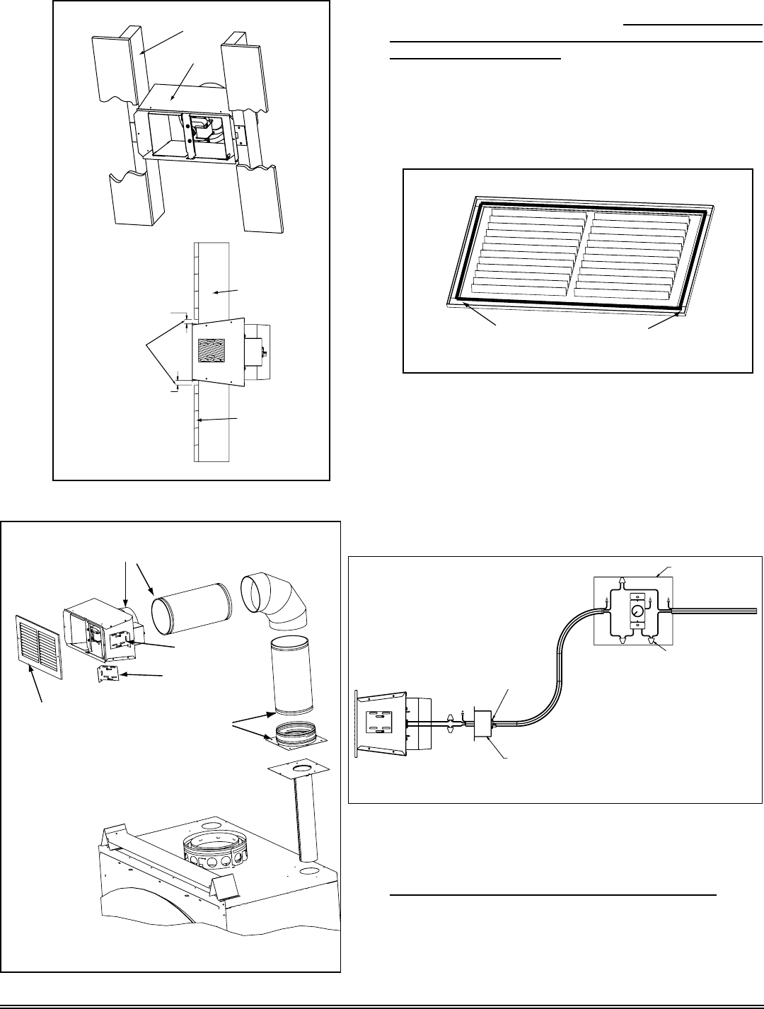
NOTE: Secure the duct so that clearance to the re-
place outer wrap is maintained. Tape all seams with
aluminum tape 1-1/4 in. (32mm) minimum width or as
specied by local codes.)
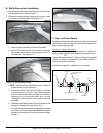
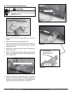
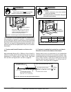
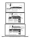
10. Seal all the way around the inside of the Return Air Grille
to prevent hot air being drawn back into the venting system
usinggasketingsuppliedwiththekit.Leave1/4in.(6mm)
clearance from all 4 outer edges. Trim excess gasketing.
See Figure 34.3.
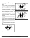
Securely Twist
Lock B-Vent to
Adapter
Secure B-Vent to Fan Housing
with sheet metal screws
Return Air Grille
Install with Louvers
pointed down
Bracket
Can rotate
180
o
2 x 4 Wall
Fan Housing
1/2in.(13mm)
clearance to
combustibles
must be
maintained.
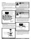
2 x 4 wall
Sheet Rock
Seal gri
lle using
gasketin
g suppli
ed with th
e kit
Leave1/4"(6mm)clearancefrom
all 4 outer edges
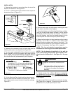
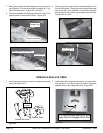
11. Install the variable speed wall rheostat (with setting on
“OFF”)inaconvenientlocation.Thisswitchwillcontrolthe
Heat-Zone fan operation.
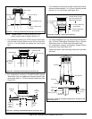
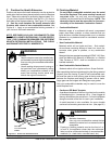
12.RemovetheJunctionBox.Wire110VACserviceTOthe
wallrheostatandFROMthewallrheostattothefanJunction
Box. Use wire nuts to secure the 110 VAC service wires to
the hot (black) and neutral (white) fan wires and screw the
110 VAC ground wire to the Junction Box. See Figure 34.4.
Figure 34.1
Figure 34.2
Figure 34.3
Junction Box Removed
Wire Clamp
Wire Nuts
Junction Box
Black
White
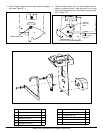
13. Secure the Return Air Grille to the fan housing making
sureitisush.Thegrillemustbeinstalledwiththelouvers
pointing down.
NOTE: DO NOT USE ADJUSTABLE REGISTERS.
14.Completethereplaceinstallationsaspertheinstruc-
tionsfoundinthisOwner’sManual.
Figure 34.4