


Page 12
Heat & Glo • NorthStar EPA Fireplace • 480-1081C
September 1, 2008
September 1, 2008
September 1, 2008
12 in.
(305mm)
42 in.
(1067mm)
43-7/8 in.
(1114mm)
24 in.
(610mm)
2 in.
(51mm)
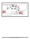
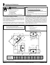
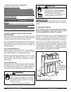
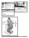
Figure 12.1 Framing the Fireplace
Position combustible /
non-combustible mantel
60 in. (1524mm) from
base of the replace
WITHIN ENCLOSURE AREA:
Appliance to backwall 1 in. (25 mm)
Appliance to sidewall 1 in. (25 mm)
Duct boots to framing 0 in. (0 mm)
Top standoffs to header 0 in. (0 mm)
Dooropeningtosidewall22-7/8in.(581mm)
EXPOSED SURFACES
Faceplate to sidewall 16 in. (406 mm)
Heat zone air grills to ceiling 12 in. (305 mm)
MANTEL
Combustible and non-combustible mantel minimum height
frombaseofreplacetoundersideofmantel
60 in. (1524 mm)
Maximummanteldepth 12in.(305mm)
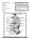
C. Frame the Fireplace
NOTE: Wiring for fans must be done before framed
enclosure is completed. If using a Heat Zone kit, it also
must be installed before enclosure is complete.
TheNorthStarFireplacewilltaframedopeningheightof
43-7/8in.(1114mm)tallandwidthof42in.(1067mm).The
nishedcavitydepthmustbenolessthan24in.(610mm).
Framing must extend straight up all the way to the ceiling.
Figure 12.1 shows a typical framing (using 2 x 4 lumber)
ofthereplace,assumingcombustiblematerialsareused.
Allrequiredclearancestocombustiblesaroundthereplace
must be adhered to. See Figure 11.1, on page 11. Any fram-
ingacrossthetopofthereplacemustbeabovethelevelof
the top standoffs. (No recess above standoffs.)
OPTIONAL FRAMING CONSTRUCTION / REDUCED
MANTEL HEIGHT:
Non-combustible mantel material minimum height from base
ofreplacetoundersideofmantel46in.(1168mm)whenthe
followingenclosureconstructionmaterialsareused:
Non-combustibleframingmaterialsmustbeusedabovere-
placetoheightof84in.(2134mm)frombaseofreplacefor
all construction materials, framing members, sheeting, and
allnishmaterials.
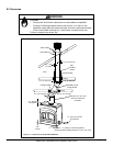
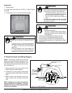
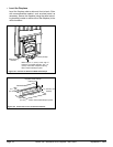
CHIMNEY SECTIONS
Chimney sections at any level require a 2 in. (51 mm) mini-
mum air space clearance between the framing and chimney
section.
Fire Risk
Hearth & Home Technologies is not respon-
sible for discoloration, cracking or other mate-
rialfailuresofnishingmaterialsduetoheat
exposure or smoke.
• Choosenishingmaterialscarefully.
WARNING
1. Minimum Clearances to Combustibles
Materialswhichwillnotigniteandburn.Suchmaterialsare
those consisting entirely of steel, iron, brick, tile, concrete,
slate, glass or plasters, or any combination thereof.
MaterialsthatarereportedaspassingASTME136,Stan-
dard Test Method for Behavior of Materials, in a Vertical
Tube Furnace at 750°C, shall be considered non-combus-
tible materials.
Materialsmadeoforsurfacedwithwood,compressedpaper,
plantbers,plastics,orothermaterialsthatcanigniteand
burn,whetherameproofedornot,orwhetherplasteredor
un-plastered shall be considered combustible materials.
Non-Combustible Materials
Combustible Materials
Fire Risk
• Non-combustible mantels installed at a
reducedheightmayGETEXTREMELY
HOTduringuseofthereplace.
• DONOTTOUCHorplaceheatsensitive
combustible items on the mantel.
WARNING