


Page 33
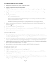
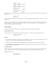
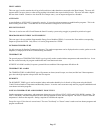
OUTPUT 7 TYPE: 0
GENERAL PURPOSE #=CHNG ↕
OUTPUT 8 TYPE: 0
GENERAL PURPOSE #=CHNG ↕
INTERIOR HORN: 4
INT SNDR #=CHNG ↕
EXTERIOR HORN: 7
EXT SNDR #=CHNG
↑
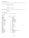
For output types, the current setting is shown on the bottom line. Press the ' # ' key to select a new type from a list of types. The
display shows:
SELECT TYPE: 6
INT SNDR ↕
Use the Up and Down arrow keys to scroll through the list, or select the appropriate output type number. Then press ' # ' to enter
the new type.
If the Interior Horn is configured as a "General Purpose" output, Unit Number 73 is used to control the output. If the Exterior
Horn is configured as a "General Purpose" output, Unit Number 74 is used to control the output. In this configuration, Unit
Numbers 73 and 74 should not be used as "Flags".
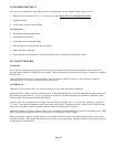
SETUP ZONES
To configure the zone type for each security zone, from the Installer Setup menu, select the 2 (ZONE) key.
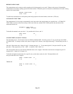
WIRELESS RECEIVER
A Wireless Receiver can be used to add 16 zones (33-48) to the Omni II. If used, you must enable the following item:
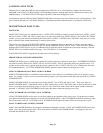
WIRELESS RECEIVER: 0
0=NO 1=YES
↓
NOTES:
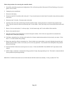
1. Up to 2 Model 10A06 Hardwire Expanders can be used with the Omni II. Zones 1-16 on the first Expander are Zones 17-32
on Omni II. Zones 1-16 on the second Expander are Zones 33-48 on Omni II.
2. When used, the Model 10A06 Hardwire Expander Modules must be configured under Setup | Installer | Expansion.
3. If a Wireless Receiver is used, a second 10A06 Hardwire Expander cannot be used also. Transmitters 1-16 on the Wireless
Receiver are Zones 33-48 on Omni II.
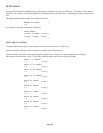
ZONE RESISTORS
This item is used to specify if the 1000-ohm end-of-line zone resistors will be used with zone inputs other than Supervised Fire
and Gas. If this item is set to "Yes", all zones other than Supervised Fire and Gas will require an end-of-line resistor.
The default setting is "Yes".
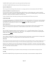
ZONE RESISTORS: 1
0=NO 1=YES ↕