


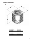

PRODUCT DESIGN
4
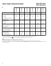
These GSH13 SEER heat pump models are shipped with a
nitrogen holding charge only and are available in 3, 4 and 5
ton sizes for 208/230 volt 3 phase applications and for 4 and
5 tons in 460 volt 3 phase.
These units are designed for free air discharge. Air is drawn
through the outdoor coil by a propeller fan, and is discharged
vertically out the top of the unit. No additional restriction
(ductwork) shall be applied.
All units come equipped with suction and liquid valves
designed for connection to refrigerant-type copper. Non-back
seating valves are factory installed to accept the field run
copper.
Systems should be properly sized by heat gain and loss
calculations made according to methods of the Air Condi-
tioning Contractors Association (ACCA) or equivalent. It is
the contractors responsibility to ensure the system has ad-
equate capacity to heat or cool the conditioned space.
GSH13 units use a mix of reciprocating and scroll compres-
sors. There are a number of design characteristics which
are different from the scroll compared to the traditional recip-
rocating compressor.
Due to their design, Scroll compressors are inherently more
tolerant of liquid refrigerant.
Note: Even though the compressor section of a Scroll com-
pressor is more tolerant of liquid refrigerant, continued
floodback or flooded start conditions may wash oil from the
bearing surfaces causing premature bearing failure.
These Scroll compressors use white oil which is compatible
with 3GS. 3GS oil may be used if additional oil is required.
GSH13 model heat pumps do not use a reversing relay to
energize the reversing valve. The reversing valve is energized
in the cooling cycle through the "O" terminal on the room
thermostat.
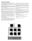
This unit is for outdoor installation only. Refer to minimum
figure for clearances from the sides of the unit to full walls
and other objects.
NOTE: This unit cannot be completely enclosed. At least
one side must be unrestricted.
These clearances will help avoid air recirculation. If installing
two or more units at the same location, allow at least 24
inches between units. If only one side is restricted (for ex-
ample, against the outside wall of a house), the unit may be
placed as close as 8" to that one wall.
DO NOT locate the unit:
* Directly under a vent termination for a gas appliance.
* Within 3 feet of a clothes drier vent
* Where the refreezing of defrost water would create
a hazard
* Where water may rise into the unit.
OK!
OK!
AA AAA
A
CC
C
C
OK!
OK!
OK!
OK!
NOT
RECOMMENDED
AA
AA
AA
AA
AA
B B B
B
Model Type A B C AA
Residential
10" 10" 18" 20"
Light Commercial
12" 12" 18" 24"
Minimum Airflow Clearance