


7
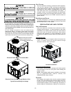
RIGGING DETAILS
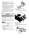
IMPORTANT NOTE: If using bottom discharge with roof curb,
ductwork should be attached to the curb prior to installing the
unit. Ductwork dimensions are shown in roof curb installation
instructions.
Refer to the Roof Curb Installation Instructions for proper curb
installation. Curbing must be installed in compliance with the
National Roofing Contractors Association Manual.
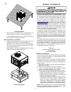
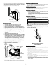
Lower unit carefully onto roof mounting curb. While rigging
unit, center of gravity will cause condenser end to be lower
than supply air end.
Rigging
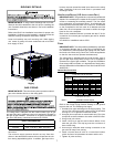
GAS PIPING
IMPORTANT NOTE: This unit is factory set to operate on natural
gas at the altitudes shown on the rating plate.
The rating plate is stamped with the model number, type of gas
and gas input rating. Make sure the unit is equipped to operate on
the type of gas available. Conversion to LP gas is permitted with
the use of the factory authorized conversion kit LPM-05.
Natural Min. 5.0" W.C., Max. 10.0" W.C.
Propane Min. 11.0" W.C., Max. 13.0" W.C.
INLET GAS PRESSURE
Inlet Gas Pressure Must Not Exceed the Maximum Value Shown in
Table Above.
The minimum supply pressure should not vary from that
shown in the table above because this could prevent the unit
from having dependable ignition. In addition, gas input to the
burners must not exceed the rated input shown on the rating
plate. Overfiring of the unit could result in premature heat
exchanger failure.
HIGH ALTITUDE DERATE (U.S. INSTALLATIONS ONLY)
IMPORTANT NOTE: The gas/electric units naturally derate with
altitude. Do not attempt to increase the firing rate by changing
orifices or increasing the manifold pressure. This can cause
poor combustion and equipment failure. At all altitudes, the
manifold pressure must be within 0.3 inches W.C. of that listed
on the nameplate for the fuel used. At all altitudes and with
either fuel, the air temperature rise must be within the range
listed on the unit nameplate.
Refer to the Installation Manual provided with the LP kit for
conversion from natural gas to propane gas and for altitude
adjustments.
Use HA02 for installations above 2000’.
PIPING
IMPORTANT NOTE: To avoid possible unsatisfactory operation
or equipment damage due to under firing of equipment, do
not undersize the natural/propane gas piping from the meter/
tank to the unit. When sizing a trunk line, include all appliances
on that line that could be operated simultaneously.
The rating plate is stamped with the model number, type of
gas and gas input rating. Make sure the unit is equipped to
operate on the type of gas available. The gas line installation
must comply with local codes, or in the absence of local codes,
with the latest edition of the National Fuel Gas Code NFPA 54/
ANSI Z223.1.
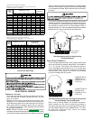
Natural Gas Connection
Len
g
th of
Pipe in Feet
1/2 3/4
1
1 1/4 1 1/2
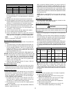
10 132 278 520 1050 1600
20 92 190 350 730 1100
30 73 152 285 590 980
40 63 130 245 500 760
50 56 115 215 440 670
60 50 105 195 400 610
70 46 96 180 370 560
80 43 90 170 350 530
90 40 84 160 320 490
100 38 79 150 305 460
Pressure = .50 PSIG or less and Pressure Drop of 0.3" W.C. (Based
on 0.60 S
p
ecific Gravit
y
Gas
)
Natural Gas Capacity of Pipe
in Cubic Feet of Gas Per Hour (CFH)
Nominal Black Pipe Size (inches)
BTUH Furnace Input
Heatin
g
Value of Gas
(
BTU/Cubic Foot
)
CFH =
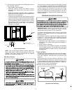
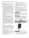
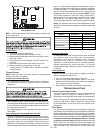
Refer to the Proper Piping Practice drawing for the general
layout at the unit. The following rules apply:
1. Use black iron pipe and fittings for the supply piping. The
use of a flex connector and/or copper piping is permitted
as long as it is in agreement with local codes.
2. Use pipe joint compound on male threads only. Pipe joint
compound must be resistant to the action of the fuel used.
3. Use ground joint unions.
4. Install a drip leg to trap dirt and moisture before it can
enter the gas valve. The drip leg must be a minimum of
three inches long.
5. Use two pipe wrenches when making connection to the
gas valve to keep it from turning.
6. Install a manual shut-off valve in a convenient location
(within six feet of unit) between the meter and the unit.
7. Tighten all joints securely.