


14
With a properly designed system, the proper amount of
temperature rise will normally be obtained when the unit is
operated at rated input with the recommended blower speed.
If the correct amount of temperature rise is not obtained, it may
be necessary to change the blower speed. A higher blower speed
will lower the temperature rise. A slower blower speed will increase
the temperature rise.
NOTE: Blower speed MUST be set to give the correct air
temperature rise through the unit as marked on the rating
plate.
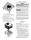
External Static Pressure Check
The total external static pressure must be checked on this
unit to determine if the airflow is proper.
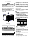
Blower Speed Adjustments
WARNING
T
O AVOID PERSONAL INJURY OR DEATH DUE TO ELECTRIC SHOCK, REMOVE
ELECTRICAL POWER FROM THE UNIT BEFORE CHANGING SPEED TAPS ON THE
BLOWER MOTOR.
Refer to the wiring diagram in the appendix to verify speed tap
settings.
Depending upon the model, blower speeds are changed at
the indoor blower. The ignition control board has four blower
speeds: LOW HEAT, HI HEAT, LOW COOL and HIGH COOL.
NOTE: FAN ONLY energizes at LOW HEAT speed.
The *PG15 models are equipped with EEM motors. EEM motors
are constant torque motors with very low power consumption.
This motor is energized by 24VAC. Adjust the CFM for the unit
by changing the 24VAC leads to the speed terminal block on the
motor.
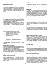
Speed
Tap
Definition
Lead
Color
Speed
Tap
Definition
Lead
Color
T1
Low
Speed Heat
White T3
Low Speed
Cool
Purple
T2
High
Speed Heat
Brown T4
High Speed
Cool
Yellow
T5
High Speed
Cool Hi-Static
HEATING COOLING
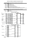
NOTE: Heating airflow must be adjusted to provide the
temperature rise shown on rating plate. A higher speed tap
may not provide more airflow. Blower speeds are
programmed to deliver adequate airflow at rated external static
pressure (ESP). Refer to airflow table provided in the Appendix
for details.
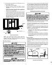
Limit Check
Check limit control operation after 15 minutes of operation
by blocking the return air grille(s).
1. After several minutes the main burners must go OFF.
Blower will continue to run.
2. Remove air restrictions and main burners will relight
after a cool down period of a few minutes.
Adjust the thermostat setting below room temperature.
1. Main burners must go OFF.
2. Circulating Air Blower will continue to run for 90, 120,
150 or 180 seconds, depending on the setting.
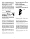
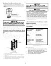
Range Nominal
Natural Low Stage 1.6 - 2.2" w.c. 2.0" w.c.
High Stage 3.2 - 3.8" w.c. 3.5" w.c.
Propane Low Stage 5.7 - 6.3" w.c. 6.0" w.c.
High Stage 9.7 - 10.3" w.c. 10.0" w.c.
Gas
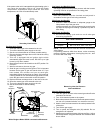
Manifold Gas Pressure
8. Remove regulator cover screw from the low (LO) outlet
pressure regulator adjust tower and turn screw clockwise
to increase pressure, or counterclockwise to decrease
pressure.
9. Energize main (M) solenoid as well as the HI terminal.
10. Remove regulator cover screw from the HI outlet pressure
regulator adjust tower and turn screw clockwise to increase
pressure, or counterclockwise to decrease pressure.
11. Turn off all electrical power and gas supply to the system.
12. Remove manometer hose from outlet pressure boss.
13. Turn outlet pressure test screw in to seal pressure port
(clockwise, 7 in-lb minimum).
14. Turn on electrical power and gas supply to the system.
15. Turn on system power and energize valve.
16. Using a leak detection solution or soap suds, check for
leaks at pressure boss screw. Bubbles forming indicate
a leak. SHUT OFF GAS AND FIX ALL LEAKS IMMEDIATELY.
NOTE: For gas to gas conversion, consult your
dealer for appropriate conversion.
Gas Input (Natural Gas Only) Check
To measure the gas input use a gas meter and proceed as
follows:
1. Turn off gas supply to all other appliances except the unit.
2. With the unit operating, time the smallest dial on the meter
for one complete revolution. If this is a 2 cubic foot dial,
divide the seconds by 2; if it is a 1 cubic foot dial, use the
seconds as is. This gives the seconds per cubic foot of
gas being delivered to the unit.
3. INPUT=GAS HTG VALUE x 3600 / SEC. PER CUBIC FOOT
Example: Natural gas with a heating value of 1000 BTU per cubic
foot and 34 seconds per cubic foot as determined by Step 2, then:
Input = 1000 x 3600 / 34 = 106,000 BTU per Hour. NOTE:
BTU content of the gas should be obtained from the gas
supplier. This measured input must not be greater than
shown on the unit rating plate.
4. Relight all other appliances turned off in step 1. Be sure
all pilot burners are operating.
Main Burner Flame Check
Flames should be stable, soft and blue (dust may cause
orange tips but they must not be yellow) and extending directly
outward from the burner without curling, floating or lifting off.
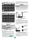
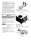
Temperature Rise Check
Check the temperature rise through the unit by placing
thermometers in supply and return air registers as close to
the unit as possible. Thermometers must not be able to
sample temperature directly from the unit heat exchangers,
or false readings could be obtained.
1. All registers must be open; all duct dampers must be in
their final (fully or partially open) position and the unit
operated for 15 minutes before taking readings.
2. The temperature rise must be within the range specified
on the rating plate.
NOTE: Air temperature rise is the temperature difference
between supply and return air.