


13
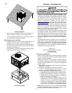
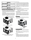
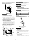
If the power to the unit is interrupted during the heating cycle, it
may cause the secondary limit to trip. Once the blower
compartment temperature drops below the limit reset
temperature, the limit will automatically reset.
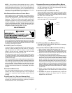
Secondary
Control Limit
Back of Unit
Secondary Limit Control
Pre-Operation Checks
1. Close the manual gas valve external to the unit.
2. Turn off the electrical power supply to the unit.
3. Set the room thermostat to its lowest possible setting.
4. Remove the heat exchanger door on the side of the unit by
removing screws.
5. This unit is equipped with an ignition device which
automatically lights the main burner. DO NOT try to light
burner by any other method.
6. Move the gas control valve switch to the OFF position. Do
not force.
7. Wait five minutes to clear out any gas.
8. Smell for gas, including near the ground. This is important
because some types of gas are heavier than air. If you
have waited five minutes and you do smell gas,
immediately follow the warnings on page 4 of this manual.
If having waited for five minutes and no gas smell is noted,
move the gas control valve switch to the ON position.
9. Replace the heat exchanger door on the side of the unit.
10. Open the manual gas valve external to the unit.
11. Turn on the electrical power supply to the unit.
12. Set the thermostat to desired setting.
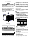
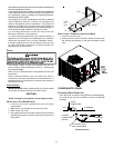
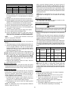
On/Off Switch
Inlet
Pressure Boss
High Fire
Coil Terminal (HI)
Low Fire
Regulator Adjust
M
a
n
o
m
e
t
e
r
M
a
n
o
m
e
t
e
r
H
o
s
e
A
High Fire Regulator
Adjust
Regulator
Vent
Common
Terminal (C)
Coaxial Coil
Terminal (M)
Outlet
Pressure Boss
Open to
Atmosphere
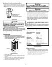
White-Rodgers Model 36G54 connected to Manometer
Gas Supply And Manifold Check
Gas supply pressure and manifold pressure with the burners
operating must be as specified on the rating plate.
Gas Inlet Pressure Check
Gas inlet pressure must be checked and adjusted in
accordance to the type of fuel being consumed.
With Power And Gas Off:
1. Connect a water manometer or adequate gauge to the
inlet pressure tap of the gas valve.
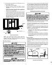
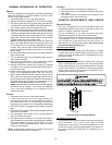
Inlet gas pressure can also be measured by removing the
cap from the dripleg and installing a predrilled cap with a
hose fitting.
With Power And Gas On:
2. Put unit into heating cycle and turn on all other gas
consuming appliances.
Natural Min. 5.0" W.C., Max. 10.0" W.C.
Propane Min. 11.0" W.C., Max. 13.0" W.C.
INLET GAS PRESSURE
NOTE: Inlet Gas Pressure Must Not Exceed the Maximum
Value Shown.
If operating pressures differ from above, make necessary
pressure regulator adjustments, check piping size, etc., and/
or consult with local utility.
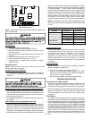
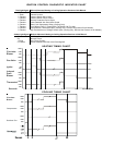
Gas Line
Gas
Shutoff
Valve
Gas Line
To Furnace
Drip Leg Cap
With Fitting
Manometer Hose
Manometer
Open To
Atmosphere
Measuring Inlet Gas Pressure
Alternate Method
Manifold Pressure Check
1 Turn OFF gas to furnace at the manual gas shutoff valve
external to the furnace.
2. Turn off all electrical power to the system.
3. Back outlet pressure test screw (inlet/outlet pressure boss)
out one turn (counterclockwise, not more than one turn).
4. Attach a hose and manometer to the outlet pressure boss
of the valve.
5. Turn ON the gas supply.
6. Turn on power and energize main (M) solenoid. Do not
energize the HI solenoid.
7. Measure gas manifold pressure with burners firing. Adjust
manifold pressure using the Manifold Gas Pressure table
shown below.