


10
UNIT VOLTAGE
The unit transformer is factory connected for 230V operation.
If the unit is to operate on 208V, reconnect the transformer
primary lead as shown on the unit wiring diagram. The induced
draft blower on some models is equipped with a low speed
230V lead (blue) and a low speed 208V lead (black). If
equipped, connect the induced draft blower low speed 208V
lead (black) in place of the low speed 230V lead (blue). Place
the unused 230V lead on the “PARK” terminal located on
ignition control.
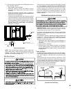
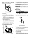
HEAT ANTICIPATOR S ETTING
The heat anticipator is to be set by measuring the load
(amperage) at the “R” circuit. Follow the instructions provided
with the thermostat for more details.
CIRCULATING AIR AND FILTERS
AIRFLOW C ONVERSION
Units can easily be converted from horizontal to down-
discharge airflow delivery. In down-discharge or high static
installations, the installer should measure the total external
static and review the blower performance charts before
performing the installation. In some installations it will be
necessary to change the blower speed to provide proper air
flow.
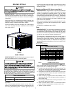
Horizontal Air Flow
Single phase models are shipped without horizontal duct
covers. If needed, these kits may be ordered through
Goodman’s Service Parts department.
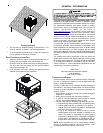
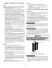
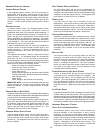
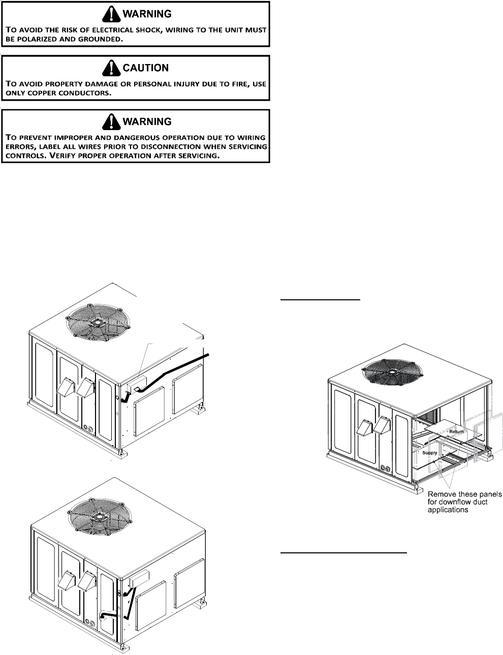
Duct Cover Installation
Down Discharge Applications
Cut insulation around bottom openings and remove panels
from the bottom of the unit, saving the screws holding the
panels in place.
NOTE: Single phase models require installation of horizontal
duct kit #20464501PDGK (medium chassis) and
#20464502PDGK (large chassis).
DUCTWORK
Duct systems and register sizes must be properly designed
for the C.F.M. and external static pressure rating of the unit.
Ductwork should be designed in accordance with the
recommended methods of Air Conditioning Contractors of
America Manual D (Residential) or Manual Q (Commercial).
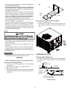
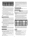
For unit protection, use a fuse or HACR circuit breaker that is in
excess of the circuit ampacity, but less than or equal to the
maximum overcurrent protection device. DO NOT EXCEED
THE MAXIMUM OVERCURRENT DEVICE SIZE SHOWN ON
UNIT DATA PLATE.
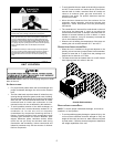
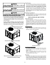
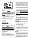
All line voltage connections must be made through
weatherproof fittings. All exterior power supply and ground
wiring must be in approved weatherproof conduit. Low voltage
wiring from the unit control panel to the thermostat requires
coded cable. See below for ground level and rooftop wiring.
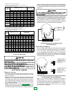
Electrical Power Directly To Junction Box
Electrical Power Routed Through Bottom of Unit
Note:Junction box location
shown is optional and is
for illustration purposes only.
JUNCTION BOX
Typical Electrical Wiring Unit Voltage