


16
ABNORMAL O PERATION - HEATING
INTERNAL C ONTROL F AILURE
If the integrated ignition control in this unit encounters an
internal fault, it will go into a “hard” lockout and turn off the
diagnostic LED. If diagnostic LED indicates an internal fault,
check power supply to unit for proper voltage, check all fuses,
circuit breakers and wiring. Disconnect electric power for five
seconds. If LED remains off after restoring power, replace
control.
EXTERNAL L OCKOUT
An external lockout occurs if the integrated ignition control
determines that a measurable combustion cannot be
established within three (3) consecutive ignition attempts. If
flame is not established within the seven (7) second trial for
ignition, the gas valve is de-energized, 30 second inter-purge
cycle is completed, and ignition is re-attempted. The control
will repeat this routine three times if a measurable combustion
is not established. The control will then shut off the induced
draft blower and go into a lockout state.
If flame is established but lost, the control will energize the
circulator blower at the heat speed and then begin a new
ignition sequence. If flame is established then lost on
subsequent attempts, the control will recycle the ignition
sequence.
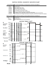
The diagnostic fault code is 1 flash for a lockout due to failed
ignition attempts. The integrated control will automatically
reset after one hour, or it can be reset by removing the
thermostat signal or disconnecting the electrical power supply
for over five seconds. If the diagnostic red LED indicates an
external lockout, perform the following checks:
• Check the supply and manifold pressures
• Check the gas orifices for debris
• Check gas valve for proper operation
• Check flame sensor
A drop in flame signal can be caused by nearly invisible
coating on the sensor. Remove the sensor and carefully
clean with steel wool.
• Check wiring
Check wiring for opens/shorts and miswiring.
IMPORTANT NOTE: If you have to frequently reset your gas/
electric package unit, it means that a problem exists that
should be corrected. Contact a qualified servicer for further
information.
PRESSURE SWITCH STUCK OPEN
A pressure switch stuck open can be caused by a faulty pressure
switch, faulty wiring, a disconnected or damaged hose, a blocked
or restricted flue, or a faulty induced draft blower.
If the control senses an open pressure switch during the pre-
purge cycle, the induced draft blower only will be energized. If
the pressure switch opens after ignition has begun the gas
valve is de-energized, the circulator blower heat off cycle
begins, and the induced draft blower remains on. The
diagnostic LED (red) code is two (2) flashes.
PRESSURE SWITCH STUCK CLOSED
A stuck closed pressure switch can be caused by a faulty
pressure switch or faulty wiring. If the control encounters a
pressure switch stuck closed, the induced draft blower
remains off. The diagnostic red LED code for this fault is
three (3) flashes.
OPEN THERMAL PROTECTION DEVICE
If a limit switch opens, the gas valve is immediately de-
energized, the induced draft and air circulating blowers are
energized. The induced draft and air circulator blowers remain
energized until the limit switch re-closes. The diagnostic LED
(red) code for an open limit is four (4) flashes.
PRIMARY LIMIT
A primary limit will open due to excessive supply air
temperatures. This can be caused by a dirty filter, excessive
duct static, insufficient air flow, or a faulty limit. Check filters,
total external duct static, blower motor, blower motor speed
tap (see wiring diagram), and limit. This limit will automatically
reset once the temperature falls below a preset level.
AUXILIARY/SECONDARY LIMIT
A dirty filter, excessive duct static, insufficient air flow, a faulty
limit, or a failed circulator blower can cause this limit to open.
Check filters, total external duct static, circulator blower motor,
blower motor speed tap (see wiring diagram), and limit. An
interruption in electrical power during a heating cycle may
also cause the auxiliary limit to open. The automatic reset
secondary limit is located on top of the circulator blower
assembly.
ROLLOUT LIMIT
If the burner flames are not properly drawn into the heat
exchanger, the flame rollout protection device will open.
Possible causes are restricted or blocked flue passages,
blocked or cracked heat exchanger, a failed induced draft
blower, or insufficient combustion air. The rollout protection
device is a manual reset limit located on the burner bracket.
The cause of the flame rollout must be determined and
corrected before resetting the limit.
FLAME DETECTED WITH GAS VALVE CLOSED
If flame is detected with the gas valve de-energized, the
combustion and air circulator blowers are energized. The
diagnostic fault code is five (5) flashes (red LED) for this
condition. The flame diagnostic LED (amber) will flash (2)
times to indicate this condition. The control can be reset by
removing the power supply to the unit or it will automatically
reset after one hour. Miswiring is the probable cause for this
fault.
LOW FLAME SIGNAL
Under some conditions, the fuel or air supply can create a nearly
invisible coating on the flame sensor. This coating acts as an
insulator causing a drop in the flame signal. If the flame signal
drops below a predetermined value, the ignition control will display
an error code of (1) flash on the amber diagnostic LED. The unit
will continue to operate until the control can no longer detect flame.
ABNORMAL OPERATION - COOLING
SHORT CYCLE COMPRESSOR DELAY
The automatic ignition control has a built-in feature that
prevents damage to the compressor in short cycling
situations. In the event of intermittent power losses or
intermittent thermostat operation, the ignition control will delay
output to the compressor contactor for three minutes from the
time power is restored or thermostat call for cooling is
restored. (Compressor is off a total of three minutes). The
diagnostic red LED will flash six (6) times to indicate the
compressor contactor output is being delayed.