


12
NORMAL SEQUENCES OF OPERATION
HEATING
This unit is equipped with an ignition control that automatically
lights the main burner. DO NOT attempt to light the main
burners by any other method.
1. Thermostat calls for low or high stage heating.
2. Induced draft blower energizes for 15-second pre-purge.
3. The spark igniter and low and high stage gas valve are
energized for 7 seconds. NOTE: The igniter produces a
very intense electrical spark that ignites the gas.
4. Main burners light and control detects presence of flame.
5. If the call is for low stage heat, the induced draft blower
switches to low speed and the high stage gas valve closes
5 seconds after the main burners light. If call is for high
stage heat, induced draft blower remains at high speed
and high stage gas valve remains open.
NOTE: If a single stage thermostat is used, the control will
step to low stage after the main burners light and remain
at low stage for 5 or 10 minutes, depending on jumper
position. If the call for HEAT remains after the transition
delay time expires, the control will transition from low stage
to high stage.
6. The 30-second HEAT FAN ON delay time begins after the
main burners light.
7. The unit delivers heat to the conditioned space until the
thermostat is satisfied.
8. Gas valve(s) de-energizes. The induced draft blower
continues operation for a 30-second post-purge.
9. Induced draft blower remains at low speed (or switches
from high to low if operating at high stage heat) for the 30-
second post purge.
10.Ignition control begins timing the HEAT FAN OFF delay.
There is an adjustable HEAT FAN OFF delay of
approximately 90/120/150/180 seconds (factory set at
150). If the unit is operating at high stage when the call for
heat is removed, the blower will operate for 30 seconds at
high heat speed then switch to low heat speed for the
remainder of the selected HEAT FAN OFF delay.
NOTE: After the HEAT FAN OFF delay time has elapsed,
the blower will de-energize. This allows any additional
heat in the heat exchanger to be transferred to the
conditioned space.
COOLING
1. Thermostat calls for low or high stage cooling.
2. If the thermostat call is for low stage cooling, the
compressor and outdoor fan are energized at low stage. If
the thermostat call is for high stage cooling, the
compressor and outdoor fan are energized at high stage.
3. The indoor blower will energize approximately 6 seconds
later.
4. The unit delivers cooling to the conditioned space until the
thermostat is satisfied.
5. The compressor and outdoor fan will be de-energized
when the thermostat opens.
6. The indoor blower continues to run at low cool speed for
approximately 60 seconds after the thermostat is satisfied.
This allows additional cooling from the indoor coil to be
transferred to the conditioned space. Then, the indoor
blower is de-energized.
NOTE: A 180-second anti-short cycle is integral to the control
and prevents recycling of the compressor.
FAN ONLY
1. Thermostat calls for FAN ONLY by energizing “G”.
2. The indoor blower is immediately energized at the low
heat speed.
3. The indoor blower is immediately de-energized once
thermostat call for FAN is removed.
STARTUP, ADJUSTMENTS, AND CHECKS
HEATING S TARTUP
This unit is equipped with an electronic ignition device to
automatically light the main burners. It also has a power vent
blower to exhaust combustion products.
On new installations, or if a major component has been
replaced, the operation of the unit must be checked.
Check unit operation as outlined in the following instructions.
If any sparking, odors, or unusual sounds are encountered,
shut off electrical power and check for wiring errors, or
obstructions in or near the blower motors. Duct covers must
be removed before operating unit.
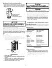
Heat Anticipator Setting
Set the heat anticipator on the room thermostat to 0.4 amps
to obtain the proper number of heating cycles per hour and to
prevent the room temperature from overshooting the room
thermostat setting.
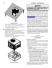
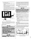
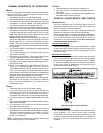
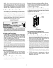
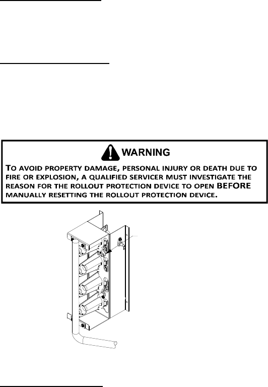
Rollout Protection Control
The rollout protection device opens, cutting power to the gas
valve, if the flames from the burners are not properly drawn
into the heat exchanger. The rollout protection device is located
on the burner bracket. The reason for elevated temperatures
at the control must be determined and repaired prior to
resetting this manual reset control.
Rollout Protection
Rollout Protection on Burner Bracket
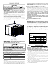
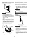
Secondary Limit Control
The secondary limit control is located on the top of the blower
scroll assembly. This control opens when elevated
temperatures are sensed. Elevated temperatures at the
control are normally caused by blower failure. The reason for
the opening should be determined and repaired prior to
resetting.