


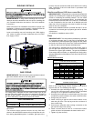
11
All ductwork exposed to the outdoors must include a weatherproof
barrier and adequate insulation.
A duct system should be installed in accordance with Standards
of the National Board of Fire Underwriters for the Installation of
Air Conditioning, Warm Air Heating and Ventilating Systems.
Pamphlets No. 90A and 90B.
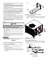
The supply duct from the unit through a wall may be installed
without clearance. However, minimum unit clearances as
shown in the appendix must be maintained. The supply duct
should be provided with an access panel large enough to
inspect the air chamber downstream of the heat exchanger. A
cover should be tightly attached to prevent air leaks.
For duct flange dimensions on the unit refer to the Unit
Dimension illustration in the appendix.
For down-discharge applications, the ductwork should be
attached to the roof curb prior to installing the unit. Ductwork
dimensions are shown in the roof curb installation manual.
If desired, supply and return duct connections to the unit may
be made with flexible connections to reduce possible unit
operating sound transmission.
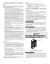
FILTERS
Even though a return air filter is not supplied with this unit,
there must be a means of filtering all return air. All units may
be externally filtered.
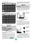
Refer to the unit filter size chart in the appendix for filter size
information.
Filters installed external to the unit should be sized in
accordance with their manufacturer recommendations. A
throwaway filter must be sized for a maximum face velocity of
300 feet per minute.
Filter Installation
IMPORTANT NOTE: When installing a filter, the air flow arrows
on the filter must point toward the circulator blower.
VENTING
NOTE: Venting is self-contained. Do not modify or block.
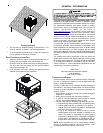
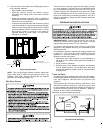
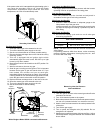
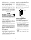
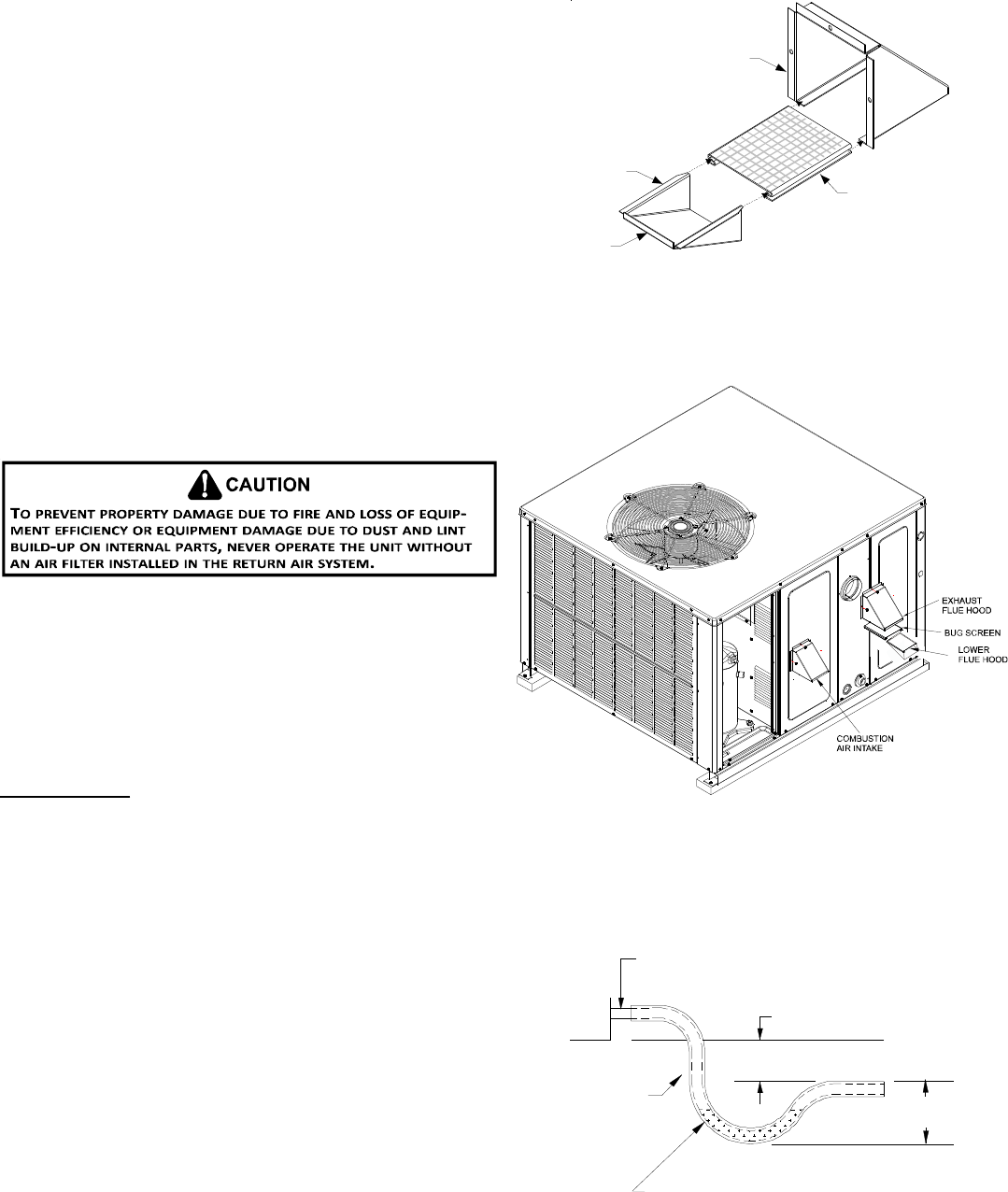
INSTALLATION - FLUE H OOD EXHAUST
1. Locate the flue hood assembly box from the blower
compartment.
2. Slide screen over flanges on the lower flue hood.
3. Slide screen into hood.
4. Using the three screws provided, attach the hood (with the
opening facing down) over the flue exhaust opening in the
utility panel.
SCREEN
HOOD
LOWER
FLUE
HOOD
LIP
INSTALLATION - COMBUSTION AIR INTAKE HOOD
1. Locate the second hood.
2. Using the three screws provided, attach the hood (with
the opening facing down) to the heat exchanger access
door.
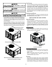
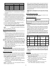
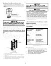
CONDENSATE DRAIN
CONDENSATE D RAIN C ONNECTION
A 3/4” NPT drain connection is supplied for condensate piping.
An external trap must be installed for proper condensate
drainage.
DRAIN
CONNECTION
UNIT 2" MINIMUM
FLEXIBLE
TUBING-HOSE
OR PIPE
3" MINIMUM
A POSITIVE LIQUID
SEAL IS REQUIRED
Drain Connection