


15
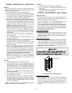
space. It is the installing contractors responsibility to ensure
the proper refrigerant sub-cooling at the condenser is adjusted
for each application. As the outdoor ambient temperature
rises the sub-cooling decreases and as the outdoor ambient
temperature lowers, the sub-cooling increases. NOTE: Proper
sub-cooling adjustment optimizes cooling performance.
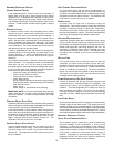
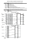
Models equipped with thermostatic expansion valve, charge
the system to sub-cooling, range shown on chart, when
necessary, adjust expansion valve stem for superheat setting.
NOTE: The expansion valve will not need adjustment for most
applications. Ensure system superheat is set within range listed
on chart.
Models# Superheat°F Subcooling°F
GPG152407041
8‐12 ‐‐‐
GPG153009041
8‐12 ‐‐‐
GPG153709041
5‐9 ‐‐‐
GPG154211541
5‐9 ‐‐‐
GPG154911541
5‐9 ‐‐‐
GPG156014041
5‐912‐18
Designsuperheat&subcooling@95°Foutdoorambienttemperature
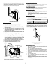
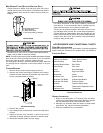
Superheat Adjustment
To adjust superheat, remove the control box cover and locate
the expansion valve on the liquid line of the evaporator.
Unscrew the cover from the expansion valve, locate the
adjustment screw, and turn it clockwise (in) to increase
superheat or counterclockwise (out) to decrease superheat.
Replace adjustment cap. Wait a minimum of 10 minutes
between adjustments to allow time for the TXV and pressures
to stabilize.
Cooling Operation
NOTE: Mechanical cooling cannot be reliably provided at
ambient temperatures below 50° F.
1. Turn on the electrical power supply to the unit.
2. Place the room thermostat selector switch in the COOL
position (or AUTO if available, and if automatic changeover
from cooling to heating is desired).
3. Set the room thermostat to the desired temperature.
TROUBLESHOOTING
IGNITION CONTROL ERROR CODES
The following presents probable causes of questionable unit
operation. Refer to Diagnostic Indicator Chart for an
interpretation of the signal and to this section for an explanation.
Remove the control box access panel and note the number of
diagnostic LED flashes. Refer to Diagnostic Indicator Chart
for an interpretation of the signal and to this section for an
explanation.
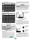
FAULT RECALL
The ignition control is equipped with a momentary push-button
switch that can be used to display on the diagnostic LED the last
five faults detected by the control. The control must be in Standby
Mode (no thermostat inputs) to use the feature. Depress the push-
button switch for approximately 2 seconds. NOTE: Do not hold
for longer than 4 seconds. Holding the button for 4 seconds
or higher will erase the memory! Release the switch when the
LED is turned off. The diagnostic LED will then display the
flash codes associated with the last five detected faults. The
order of display is the most recent fault to the least recent
fault.
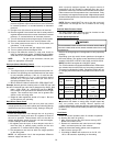
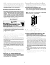
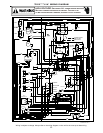
LO COOL
HI COOL
LO HEAT
HI HEAT
U6
U7
U4
U5
U3
K2
K1
P1
ECON
STAGE
DELAY
SPEEDUP
SW1
FAULT
RECALL
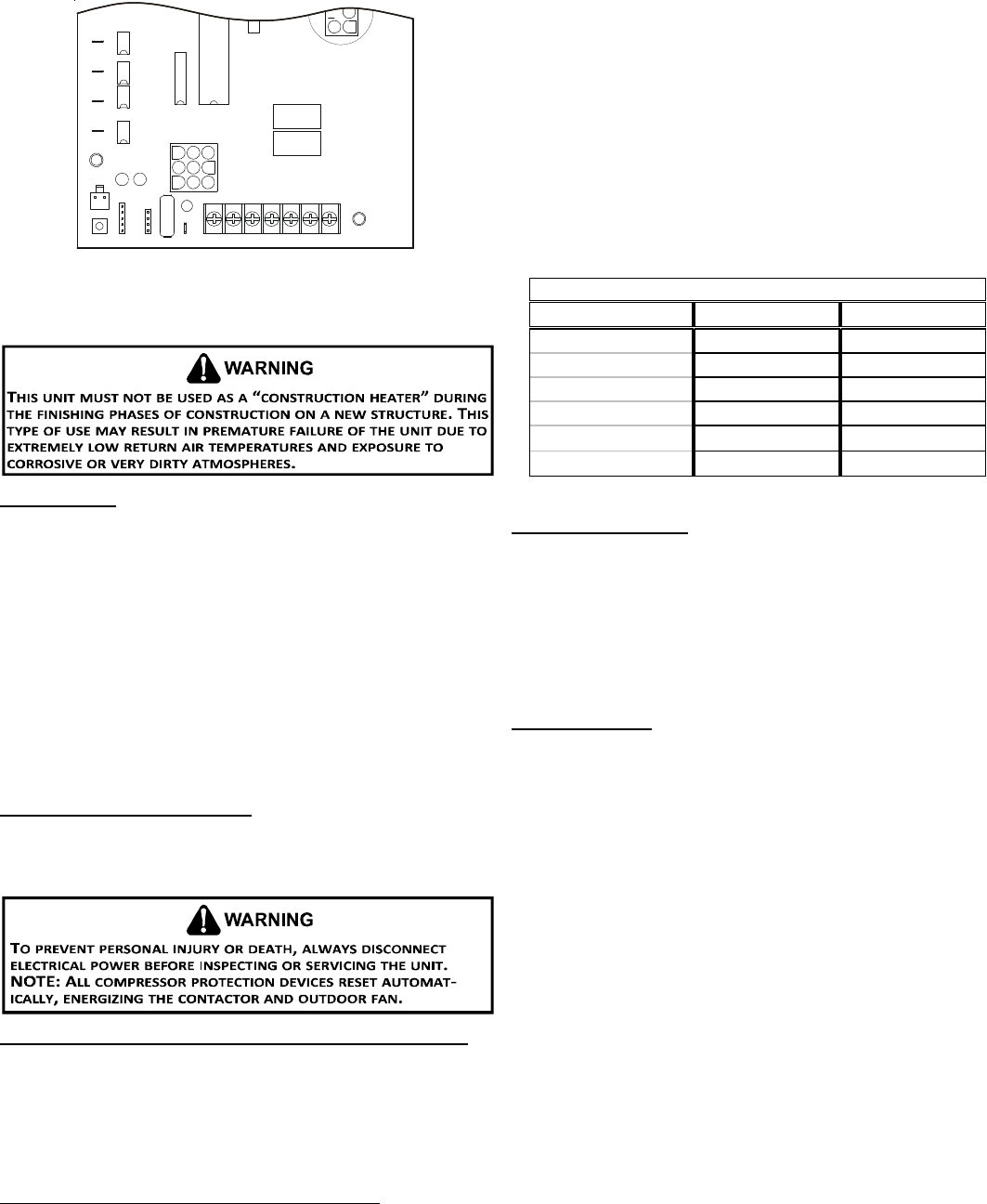
BLOWER
OFF DELAY
F1
RCW1W2
GY1Y2
Control Board (Top)
NOTE: If necessary, adjust fan OFF delay settings to obtain satis-
factory comfort level.
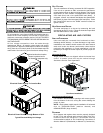
Unit Shutdown
1. Set the thermostat to lowest setting.
2. Turn off the electrical power supply to the unit.
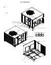
3. Remove the heat exchanger door on the side of the unit by
removing screws.
4. Move the gas control valve switch to the OFF position. Do
not force.
5. Close manual gas shutoff valve external to the unit.
6. Replace the heat exchanger door on the unit.
7. If cooling and/or air circulation will be desired, turn ON the
electrical power.
COOLING S TARTUP
NOTE: Check all manual reset limit controls in heating circuit if
cooling mode does not operate.
Compressor Protection Devices
The compressor includes components which are designed
to protect the compressor against abnormal operating
conditions.
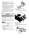
Refrigerant Charge Check (Units with Fixed Orifice Devices)
After completing airflow measurements and adjustments the
unit’s refrigerant charge must be checked. All package units with
fixed orifice devices are charged using the super heat method at
the compressor suction line.
For charge adjustments, see superheat and charts shown for
each model.
Cooling Refrigerant Charging (Models with TXV)
Check unit charge before putting the cooling section into full
operation. The unit has a thermostatic expansion valve metering
device. To ensure the unit is properly charged for the intended
application, check the unit refrigerant sub-cooling at the
condenser. The refrigerant sub-cooling is a function of outdoor
ambient temperature and return air temperature of the conditioned