


17
NOTE: Some electronic thermostats also have a built-in
compressor short cycle timer that may be longer than the
three minute delay given above. If you are using an electronic
thermostat and the compressor has not started after three
minutes, wait an additional five minutes to allow the
thermostat to complete its short cycle delay time.
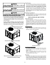
HIGH PRESSURE SWITCH/LOSS OF CHARGE SWITCH
Some models include a high pressure cutout switch and/or a
loss of charge cutout switch. The high pressure cutout switch
protects the refrigeration system from excessive operating
pressures. The loss of charge cutout switch protects the
refrigeration system from very low operating pressures due
to a loss of refrigerant. Compressor operation will be disabled
if either of these devices opens. If either devices opens, the
diagnostic red LED will flash (9) times to indicate that a
refrigeration system pressure switch is open.
MAINTENANCE
Have the gas heating section of the unit checked at least
once a year before the heating season begins, to be sure that
the combustion air inlet and flue outlet hoods are not blocked
by debris, which would prevent adequate combustion air and
a properly operating vent system.
FILTER REPLACEMENT OR CLEANING
A return air filter is not supplied with this unit; however, there
must be a means of filtering all of the return air. The filter(s)
may be located in the return air duct(s), or return air filter
grille(s). Consult with your installing dealer for the actual
location of the return air filter(s) for your unit.
Dirty filters are the most common cause of inadequate heating
or cooling performance. Filter inspection should be made at
least every two months; more often if necessary because of local
conditions and usage.
Dirty throwaway filters should be discarded and replaced with a
new, clean filter. Dirty permanent filters should be washed with
water, thoroughly dried and sprayed with a filter adhesive before
being reinstalled. (Filter adhesives may be found at many
hardware stores.) Permanent filters should last several years.
However, should one become torn or uncleanable, it should be
replaced.
CABINET F INISH M AINTENANCE
Use a fine grade automotive wax on the cabinet finish to
maintain the finish’s original high luster. This is especially
important in installations with extended periods of direct
sunlight.
CLEAN OUTSIDE COIL (QUALIFIED SERVICER ONLY)
The coil with the outside air flowing over it should be inspected
annually and cleaned as frequently as necessary to keep the
finned areas free of lint, hair and debris.
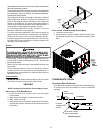
CONDENSER, EVAPORATOR, AND INDUCED DRAFT MOTORS
Bearings on the air circulating blower motor, condenser motor
and the combustion fan motor are permanently lubricated.
No additional oiling is required.
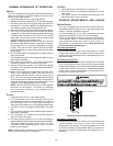
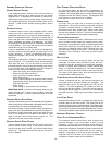
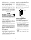
FLAME SENSOR (QUALIFIED SERVICER ONLY)
A drop in the flame current can be caused by a nearly invisible
coating on the flame sensor. This coating, created by the fuel
or combustion air supply, can be removed by carefully cleaning
the flame sensor with steel wool.
NOTE: After cleaning, the microamp signal should be stable
and in the range of 4 - 6 microamps DC.
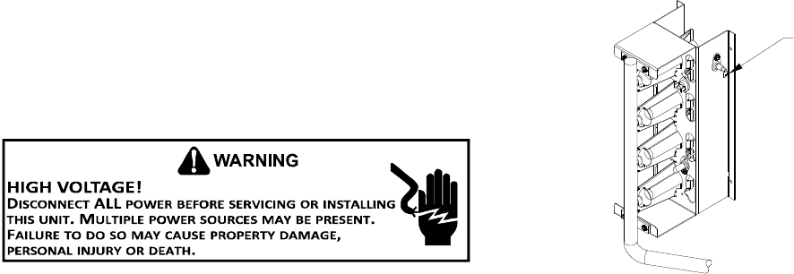
Flame
Sensor
Flame Sensor
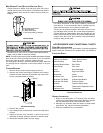
FLUE PASSAGES (QUALIFIED SERVICER ONLY)
At the start of each heating season, inspect and, if necessary,
clean the unit flue passage.
CLEANING FLUE PASSAGES (QUALIFIED SERVICER ONLY)
1. Shut off electric power and gas supply to the unit.
2. Remove burner assembly by disconnecting the gas line
and removing the manifold bracket from the partition panel.
3. Remove the flue from the induced draft blower and the
collector box cover from the partition panel.
4. The primary heat exchanger tubes can be cleaned using a
round wire brush attached to a length of high grade stainless
steel cable, such as drain cleanout cable. Attach a variable
speed reversible drill to the other end of the spring cable.
Slowly rotate the cable with the drill and insert it into one of
the primary heat exchanger tubes. While reversing the drill,
work the cable in and out several times to obtain sufficient
cleaning. Use a large cable for the large tube, and then repeat
the operation with a small cable for the smaller tube. Repeat
for each tube.
5. When all heat exchanger tubes have been cleaned,
replace the parts in the reverse order in which they were
removed.
6. To reduce the chances of repeated fouling of the heat
exchanger, perform the steps listed in “Startup,
Adjustments, and Checks”.