4
Safe-T-Beam
®
(STB) Non-Contact Reversing System
Places an invisible beam across door opening that reverses the door during down travel to the fully open
position if anything passes through beam.
Safe-T-Reverse
®
Contact Reversing System
Automatically stops and reverses a closing door within 2 seconds of contact with an object.
Safe-T-Stop
®
Timed Reversed System
Automatically opens a closing door, if door does not close within 30 seconds.
Force Guard
®
Control
Used to set the force required for opening and closing door. For maximum safety, set the minimum force
required to fully open and close door.
Automatic Lighting System
Two light bulbs up to 60 Watts max. each are used for safer entries and exits. The light turns on when door is
activated and automatically turns off 4.5 minutes later.
Manual Emergency Release
Allows the garage door to be opened or closed manually for emergencies or maintenance.
SAFETY FEATURES
(
varies by model
)
TABLE OF CONTENTS
SECTION PAGE
PRE-INSTALLATION CHECK LIST . . . . . . . . . . . . . . . . 2-3
TOOLS REQUIRED . . . . . . . . . . . . . . . . . . . . . . . . . . . . . . 4
SAFETY FEATURES . . . . . . . . . . . . . . . . . . . . . . . . . . . . . . . . 4
OPERATIONAL FEATURES . . . . . . . . . . . . . . . . . . . . . . . . . . 5
PARTS LISTS AND ILLUSTRATIONS . . . . . . . . . . . . . . . . . 5-8
POWER HEAD . . . . . . . . . . . . . . . . . . . . . . . . . . . . . . . . . . 5
ONE-PIECE RAIL . . . . . . . . . . . . . . . . . . . . . . . . . . . . . . . . 6
THREE-PIECE RAIL . . . . . . . . . . . . . . . . . . . . . . . . . . . . . . 7
FASTENERS AND ACCESSORIES . . . . . . . . . . . . . . . . . . 8
SAFETY INFORMATION . . . . . . . . . . . . . . . . . . . . . . . . . . . . . . 9
PRE-INSTALLATION WARNING . . . . . . . . . . . . . . . . . . . . . . . . 9
1MAIN ASSEMBLY . . . . . . . . . . . . . . . . . . . . . . . . . 10-14
2INSTALLATION . . . . . . . . . . . . . . . . . . . . . . . . . . . 15-21
3 SAFE-T-BEAM
®
. . . . . . . . . . . . . . . . . . . . . . . . . . . 22-23
4WALL CONTROL . . . . . . . . . . . . . . . . . . . . . . . . . . 24-25
5 LIGHT & LIGHT LENS. . . . . . . . . . . . . . . . . . . . . . . . . 25
6 CONNECTING POWER . . . . . . . . . . . . . . . . . . . . . . . . 26
7 SETTINGS. . . . . . . . . . . . . . . . . . . . . . . . . . . . . . . . 27-28
CONTACT REVERSE. . . . . . . . . . . . . . . . . . . . . . . 28
8BATTERY & VISOR CLIP. . . . . . . . . . . . . . . . . . . . . . . 28
9PROGRAMMING REMOTE CONTROLS . . . . . . . . . . 29
TRANSMITTER COMPLIANCE STATEMENT . . . . . . . . . . . . 30
IMPORTANT SAFETY INSTRUCTIONS . . . . . . . . . . . . . . . . . 30
10 MAINTENANCE & TROUBLESHOOTING . . . . . . . 31-32
11 WIRING DIAGRAM . . . . . . . . . . . . . . . . . . . . . . . . . . . . A
WARRANTY B
ACCESSORIES ORDER FORM . . . . . . . . . . . . . . . . . . . . . . . . C
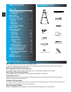
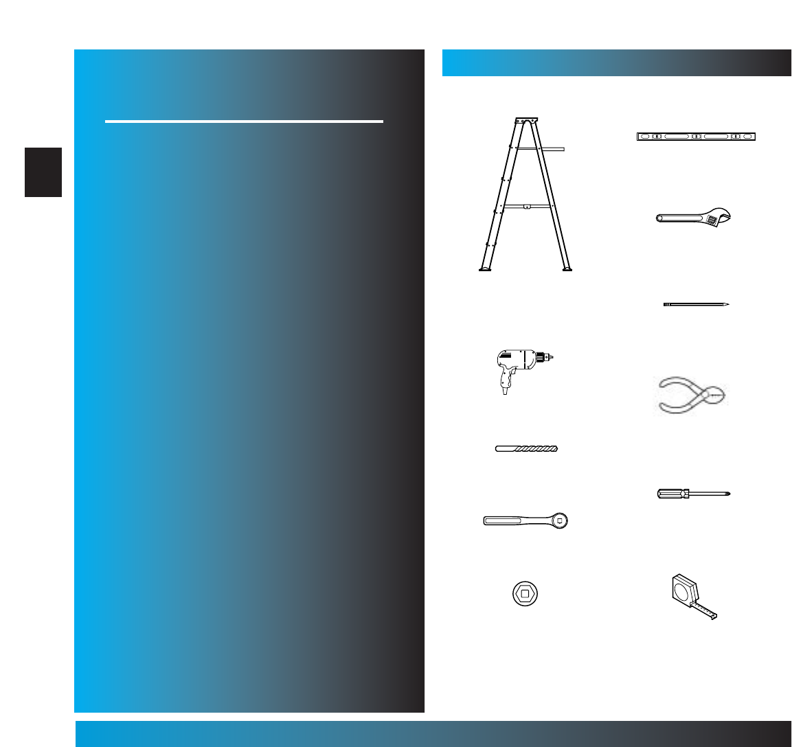
RECOMMENDED TOOLS
5/ 32" Drill Bit
7/16" and 9/16" Sockets
Step ladder
Drill
Ratchet
Carpenter’s level
Pencil
Tape measure
Wire strippers
Phillips screwdriver
Adjustable wrench


