


24
SECT 4—WALL CONTROL INSTALLATION
FOR HELP- 1.800.354.3643
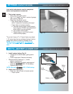
Fig. 4-1
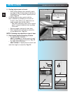
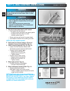
1. Run wire from power head to wall control
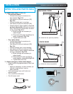
• Find location for wall control:
–In sight of door and away from moving parts.
– At least 5 feet from floor, so small
children cannot reach it.
• Route wire from wall control to power head.
• Use staples to fasten wire to ceiling and wall.
NOTE: Use only staples included
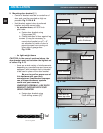
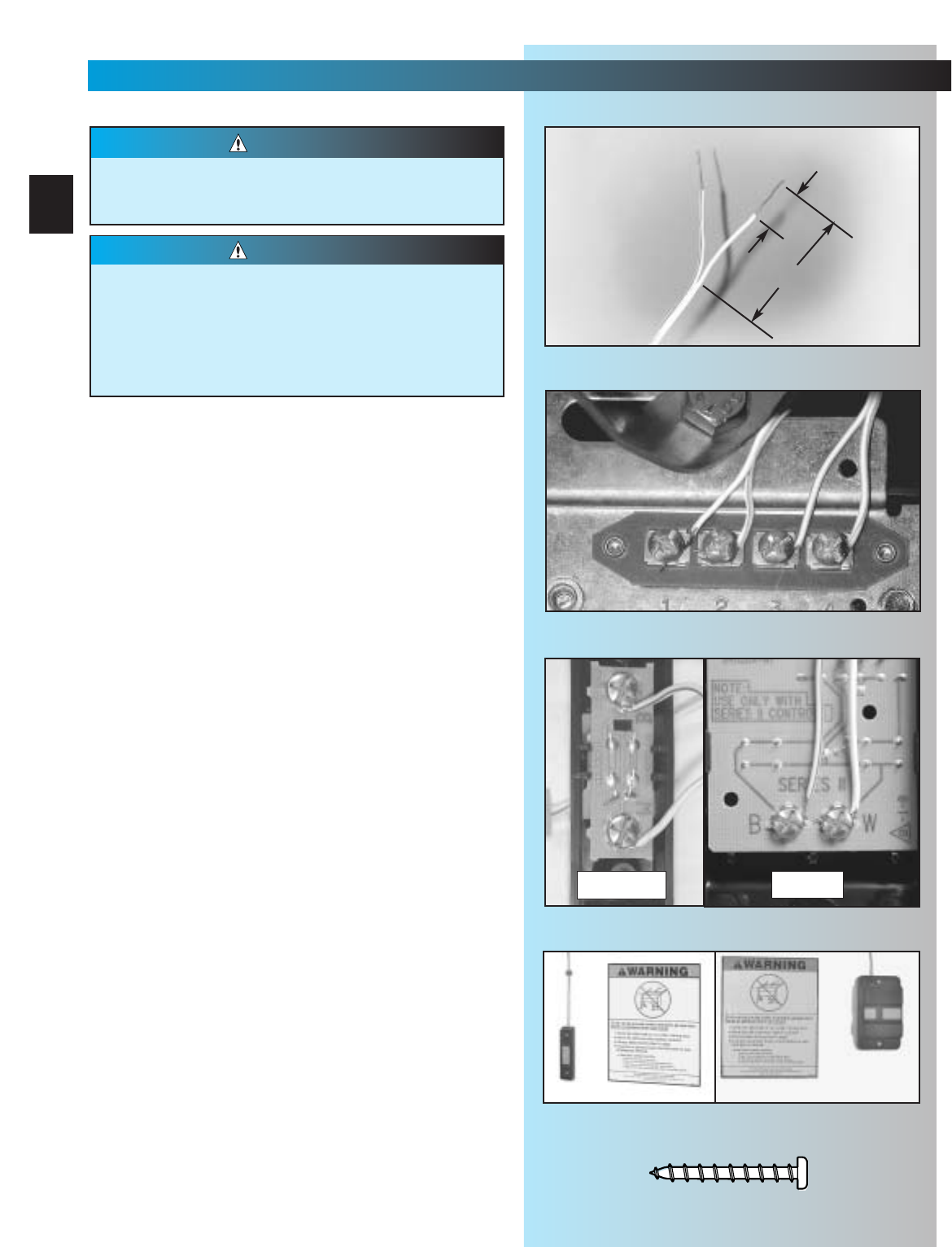
2. Split wires at ends and remove 1/2 inch of
insulation from end of each Wire. Fig. 4-1.
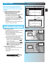
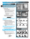
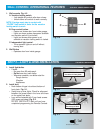
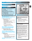
3. Attach wires to terminals. Fig. 4-2, Fig. 4-3.
• Loosen (Do Not Remove) screws from
Terminals at power head and wall control
• Connect wires to power head
– White wire to terminal
#
1
–Striped wire to terminal
#
2
– Tighten screws
• Connect wires to wall control
– Striped wire to terminal “B”
– White wire to terminal “W”
– Tighten screws
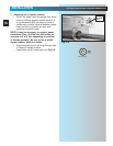
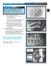
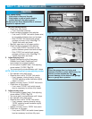
4. Mount wall control. Fig. 4-4.
•For Wall Console or Wall Button.
– Use pan head screws [34].
5. Mount entrapment warning label. Fig. 4-4.
• Remove protective backing.
• Stick label to wall next to wall control.
–Tacks or staples may be required on some
rough texture surfaces.
NOTE: Additional wall controls are available from
your dealer. ONLY ONE OF YOUR WALL CONTROLS
MAY BE THE LIGHTED TYPE. If you have a lighted
wall control, all your additional controls must be
un-lighted. More than one lighted wall control per
operator will cause a malfunction.
Power must be removed before attaching wires.
Be sure ends do not touch each other or other
terminals.
WARNING
•Use of any other wall control can cause the
door to operate unexpectedly and the light
not to work.
•Cut or pinched wires can cause door
operator to malfunction. Drive staples just
tight enough to hold wire.
CAUTION
1/2"
1-1/4” to 1-1/2"
Fig. 4-2
button
console
Fig. 4-3
Fig. 4-4
#6 x 1-1/4" Pan head screw
[
34
]