


14
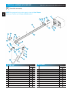
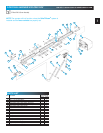
MAIN ASSEMBLY
FOR HELP-1.800.354.3643 OR GENIECOMPANY.COM
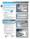
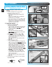
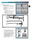
14. Attach emergency release knob, cord
and tag.
•Tie an overhand knot in one end of
emergency release cord [17].
–
Slide cord through center of knob
[18]
.
Fig. 1-17.
– Slide cord through hole in emergency
release lever (on carriage).
– Tie a second knot in this end. Fig. 1-18.
– Slip wire of emergency release tag [19]
through hole in emergency release lever
and twist it around itself.
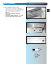
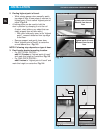
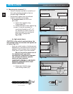
15. Attach limit switches.
•“CLOSE” limit switch
[15B]
.
(Switches are identical.)
– Place “CLOSE” limit switch over top of rail
about 12 inches from r
ail strap. Fig. 1-19.
– Check that white lever is toward
power head.
–Insert set screw [16] into limit switch
hand
tight only to temporarily hold switch
in place. Fig. 1-19A.
– Attach bro
wn wire to switch. Fig. 1-19B.
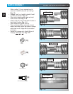
– Leaving some slack in wire (Fig. 1-20),
run wire down inside groove in top of rail
back to power head.
– Use wire clip [44] to help maintain slack.
Fig. 1-20.
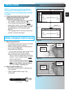
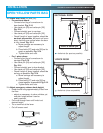
•“OPEN” limit switch
[15A]
.
– Place “OPEN” limit switch over top of rail
about 12 inches from po
wer head. Fig.1-21.
– Check that white lever is on side away from
power head. (This means limit switches
hang off opposite sides of rail. Check this
to help verify they are installed properly.)
–Insert set screw [16] into limit switch hand
tight only to temporarily hold switch in place.
– Attach gre
y wire to switch. Fig. 1-21.
– Leaving some slack in wire (Fig. 1-21),
run wire down inside groove in top of rail
back to power head.
– Use wire clip [44] to help maintain slack.
Fig. 1-21.
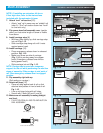
• Coil excess wire and tape it to top of power
head. Fig. 1-21A.
Fig. 1-19
A
B
Fig. 1-20
wire clip
pow
er head
Fig. 1-21
A
“close”
switch
“open”
switch
set screw
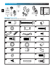
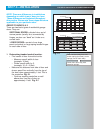
OPEN GREEN PARTS BAG
Screws for attaching light cover are included in this bag.
Please set aside for use later.
grey wire
brown wire
Fig. 1-17
Fig. 1-18
release
knob
tag
cord
#8-32 x 3/8" Hex head screw
Wire clip
[
16
]
[
44
]