


23
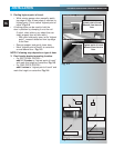
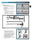
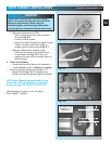
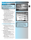
• Make wire attachments at STBs.
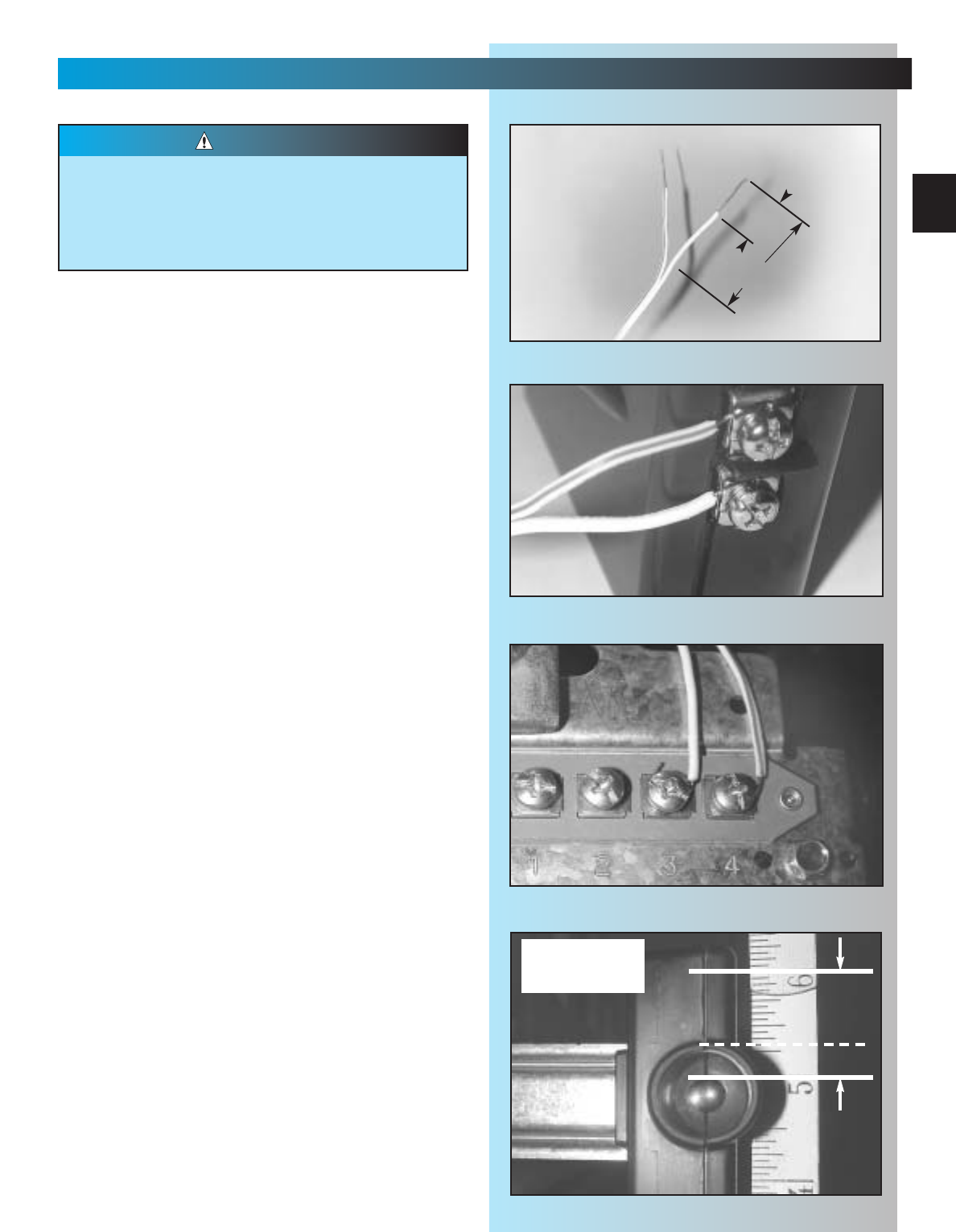
– Split and strip wire ends to be connected
as shown Fig. 3-6.
– Loosen terminal screws.
– Insert wire under flat plate and tighten screw.
It does not matter which wire, white or
striped, goes on which terminal Fig. 3-7.
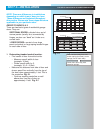
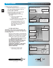
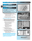
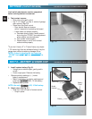
• Make wire attachments at power head.
– STBs are connected to terminals #3 and
#4 on power head Fig. 3-8. It does not
matter which wire, white or striped, goes on
which terminal.
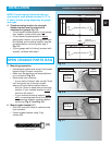
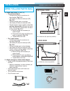
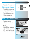
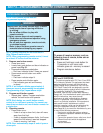
4. Check the following.
• Ensure that no part of door or its hardware is
in path between lenses of source and sensor.
• Ensure that tops of lenses are between 5"-6"
above the floor Fig. 3-9. The brackets are
flexible, and can be adjusted slightly if needed.
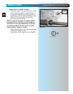
NOTE: Safe-T-Beam® alignment check will be
performed following connection to electrical
power (see page 26). DO NOT PLUG IN YET!
(See Illustration on page 3 for a full view of
Safe-T-Beam
®
location.)
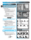
Staples which are too tight can cut or pinch
wires. Cut or pinched wires can cause the STB
System to stop working. When using the
insulated staples, make sure you fasten them
only as tightly as needed to hold the wire snugly.
CAUTION
SAFE-T-BEAM
®
INSTALLATION
FOR HELP- GENIECOMPANY.COM
top edge of lens
between 5" - 6"
above floor.
Fig. 3-6
≈1-1/4" to 1-1/2"
≈1/2"
Fig. 3-7
Fig. 3-8
Fig. 3-9