


17
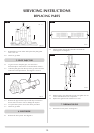
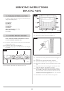
2.4 Raise the burner from the slot in the bracket, pull the
burner forward and slide to the left to clear the injector.
Take care not to lose the spring.
2.5 Replace in reverse order ensuring the spring is located over
the stud on the burner and the tab on the bracket.
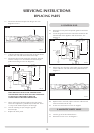
The main frame, glass frame and main burner need only be
removed if the pilot burner is to be replaced. If only the
pilot injector, electrode or thermocouple is to be replaced
they can be accessed from under the appliance.
The pilot assembly consists of four components, which can
be individually changed, these are:
1) Pilot burner bracket.
2) Pilot injector
3) Electrode
4) Thermocouple.
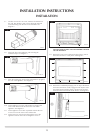
4.1 Remove the main front by referring to the instructions
supplied with the decorative front.
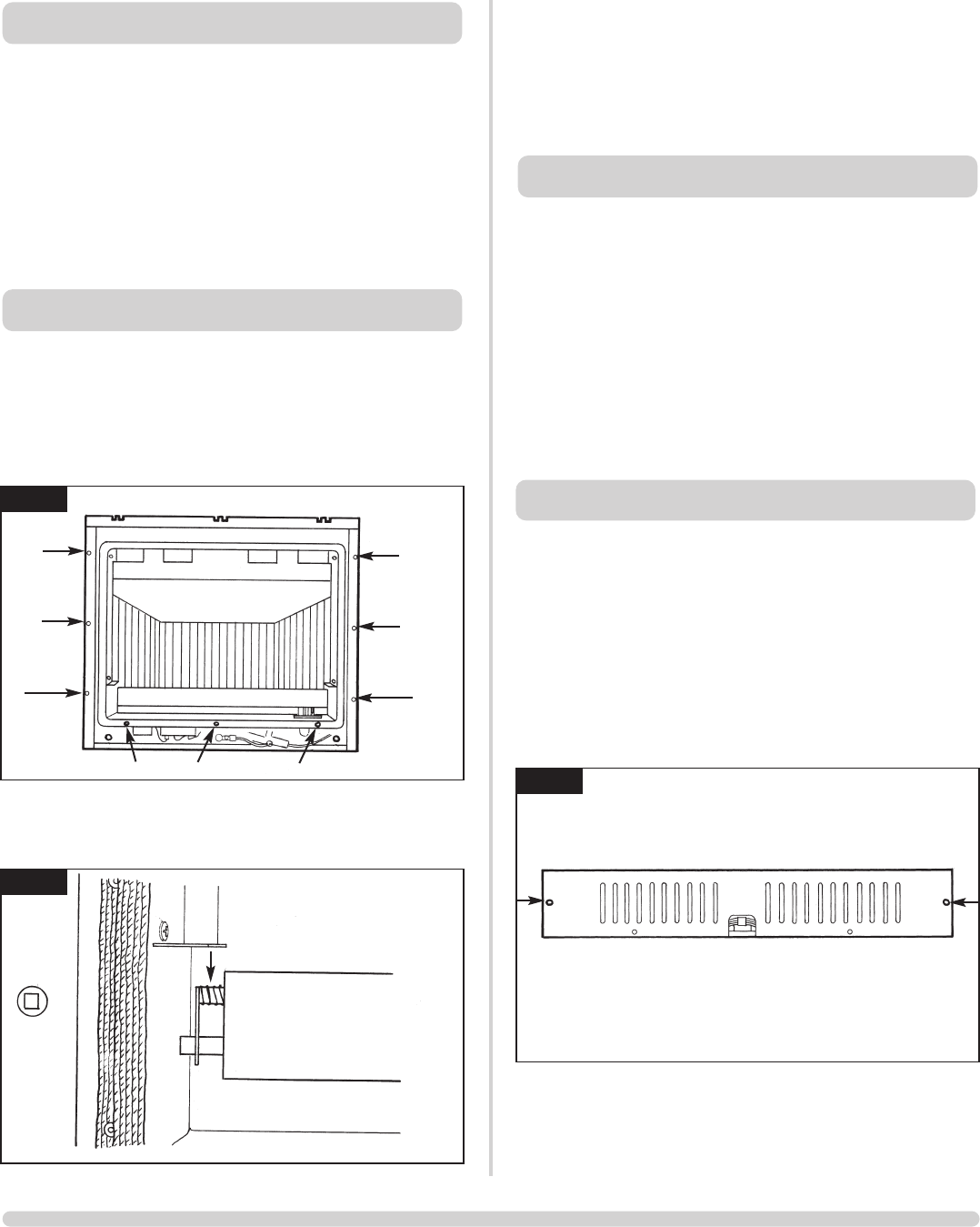
4.2 Remove the glass frame from the appliance. See diagram 1
arrow C.
4.3 Remove the main burner by compressing the spring on the
lefthand side of the burner. See diagram 2. Raise the burner
forward and slide to the left to clear the injector. Take care
not to lose the spring.
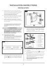
4.4 Working underneath the appliance, remove the lower
cover. See diagram 3.
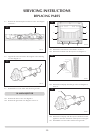
4.5 Remove the thermocouple, pilot pipe and electrode as
described in the sections 5 to 7.
4.6 Remove the two screws retaining the pilot burner. See
diagram 4.
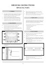
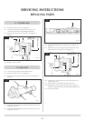
3. PILOT UNIT
1.1 All principal components can be replaced without removing
the appliance from its installation, although it is essential
that the gas supply to the appliance is turned off at the
isolation device before proceeding further.
1.2 If for any reason the flue has to be removed from the
appliance, the seal must be replaced in the inner spigot.
1.3 If access to the controls is restricted, the whole control
assembly and wiring loom can be removed and serviced
outside the Linea, refer to section 14 for further details.
2.1 Remove the front from the appliance. (Refer to the
instructions supplied with the decorative front)
2.2 Remove the glass frame, note the orientation of the screws.
The three long silver screws locate only in the bottom of the
frame. See diagram 1, arrow C.
2.3 Compress the burner retaining spring towards the burner.
See diagram 2.
2. MAIN BURNER
1. GENERAL
SERVICING INSTRUCTIONS
REPLACING PARTS
4. PILOT BURNER
1
AR1338
3
AR1341
2
AR1340
C
C
C
C
C
C
C
C
C