


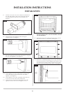
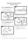
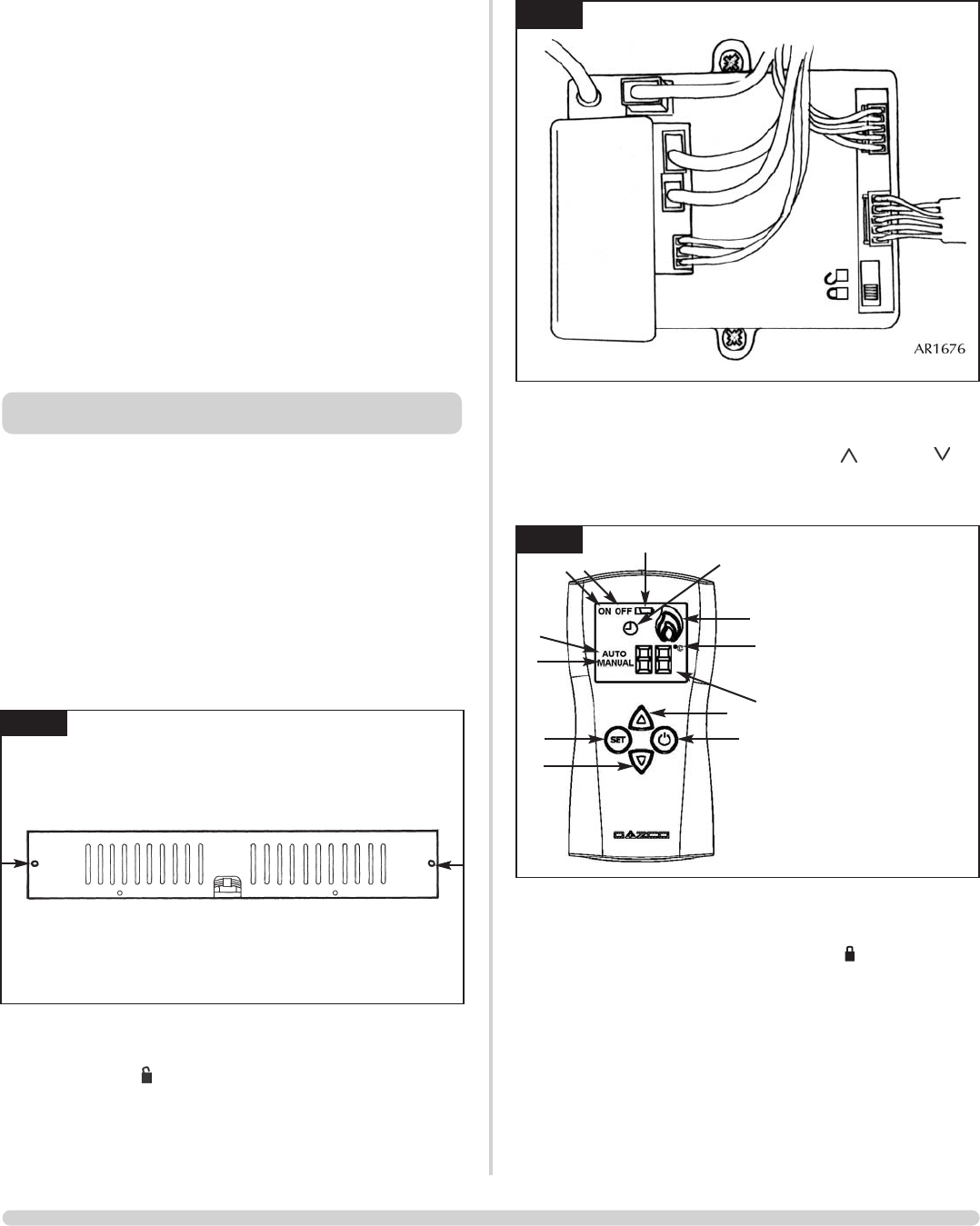
3.1.3 The remote handset must now be programmed. Push the ON /
OFF button (11), the ON or OFF display will start flashing. Then
press the ON / OFF button (11), and the
( )
(10) and
( )
(13) buttons at the same time.
Immediately after press the SET button (12) once. See diagram
11.
3.1.4 The clock (7) will appear on the display. After a few seconds this
will disappear.
3.1.5 Finally push the switch back to the Locked position, towards
the rear of the appliance. The remote should now be tuned to
the control box.
3.1.6 Replace the lower cover; ensure the tabs are located on the rear
flange. Engage the front tabs at the side of the appliance and
replace the two screws. Take extreme care as to not trap any
cables when replacing the cover.
NOTE: IF A NEW HANDSET IS PURCHASED THE ABOVE
PROCEDURE MUST BE REPEATED.
3.2 Check flame picture.
3.3 Check gas pressure.
14
INSTALLATION INSTRUCTIONS
INSTALLATION
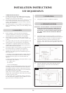
NOTE: THE HANDSET HAS BEEN FACTORY
PROGRAMMED TO OPERATE THIS FIRE. IF
THE HANDSET OR CONTROL UNIT HAS
BEEN REPLACED, YOU MUST FOLLOW THE
PROGRAMMING PROCEDURE.
3.1 Programming the handset
Section 3 must be read in total before trying to program the
hand set. The sequence must be performed while the ON /
OFF on the display is still flashing.
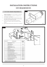
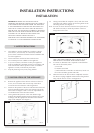
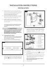
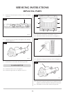
3.1.1 Remove the two outer screws from the under side of the
appliance, pull the cover forward and remove. See diagram 9.
3.1.2 Working under the appliance the control box is located on the
left hand side. Using a pen or something similar push the switch
to the Unlock position. When viewed from underneath the
ON position is towards the front of the appliance. See diagram
10.
3. COMMISSIONING
9
AR1341
10
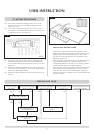
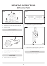
2.15 Replace the glass frame; ensure the top of the frame is
hooked on the tabs at the top of the appliance and replace
the nine screws with the three longest screws used in the
bottom fixing holes. Tighten from the top down.
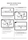
HAVE YOU PURGED THE GAS SUPPLY?
2.16 Connect the gas supply to the isolation device using 8mm
pipe. Connect a suitable pressure gauge to the test point
and turn on the gas supply and check for leaks.
2.17 Light the appliance and set it to maximum. Check the
pressure corresponds to the data badge. Turn the gas off
and replace the test point screw. Turn the gas on and check
the screw for leaks.
THE YELLOW FLAMES WILL APPEAR WHEN THE FIRE
HAS GAINED SUFFICIENT HEAT - TYPICALLY 20
MINUTES.
26
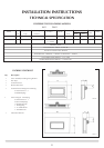
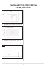
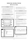
1: Flame display
2: Celsius display
3: Temperature display
4: On display
5: Off display
6: Low battery display
7: Clock display
8: Auto display
9: Manual display
10: UP button
11: ON/OFF button
12: SET button
13: DOWN button
AR1665
1
2
3
10
11
5
6
7
4
8
9
12
13