


10
TIMBER FRAMED BUILDINGS
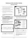
1.5 It will be necessary to provide additional clearance when
the flue passes through a wall containing any combustible
materials so as to prevent a fire hazard.
1.6 The hole through which the flue will pass, must have a steel
sleeve which is positioned so that an air gap of at least
25mm is maintained between the outer surface of the flue,
and any part of the sleeve.
1.7 For further guidance on the installation of gas appliances in
timber framed buildings, contact your local buildings control
authority.
2.1 Before installation, ensure that the local distribution
conditions (identification of the type of gas and pressure)
and the adjustment of the appliance are compatible.
2.2 Ensure that the gas supply is capable of delivering the
required amount of gas and is in accordance with the rules
in force.
2.3 Soft copper tubing can be used to install the appliance. Soft
soldered joints can be used externally of the appliance.
2.4 This appliance is supplied complete with a factory fitted
isolation device incorporated into the inlet connection, no
further isolation device is required.
2.5 All supply gas pipes must be purged of any debris that may
have entered, prior to connection to the appliance.
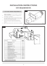
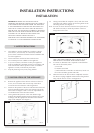
2.6 The gas inlet is located centrally at the bottom of the
appliance. The supply pipe may be installed using one of
three alternatives.
1) By drilling a hole straight through the outside wall. There
is a cutout in the back panel of the Linea and the fixing
bracket to allow the pipe to be concealed within the
appliance.
2) Surface mounting the pipe. For this option there is a pipe
cover kit 8654. This consists of
a) 1.4 Metre Cover
b) 2 Brackets
c) Screws and Rawlplugs
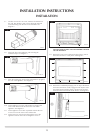
To fit the cover, measure the length required and cut down
accordingly. Fix the two brackets to the wall as required.
The magnets should be vertical. Fix pipe clips to the wall
and install the gas pipe. The cover can now be attached to
the magnets to cover the gas supply.
NOTE: There are three options of cover finishes. Black,
Metallic Alloy and primed finish which allows the customer
to finish any chosen colour.
3) The gas pipe can be concealed by cutting a channel in
the wall. All current regulations must be adhered to and no
pipe joint must be concealed in the wall.
2. GAS SUPPLY
INSTALLATION INSTRUCTIONS
SITE REQUIREMENTS
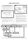
3.1 This appliance requires no additional ventilation.
IMPORTANT: DO NOT OBSTRUCT THE TOP AND BOTTOM
SLOTS IN THE LINEA OUTER CASE, THESE MUST BE
UNOBSTRUCTED. DO NOT RECESS THIS APPLIANCE
INTO A WALL, IT MUST BE SURFACE MOUNTED ON A
FLAT WALL USING THE WALL MOUNTING BRACKET
SUPPLIED.
4.1 This appliance does not require a hearth. It can only be
fitted on an outside wall with suitable clearances for the flue
terminal and guard (if required). As detailed in diagram 1.
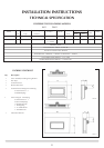
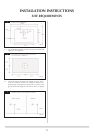
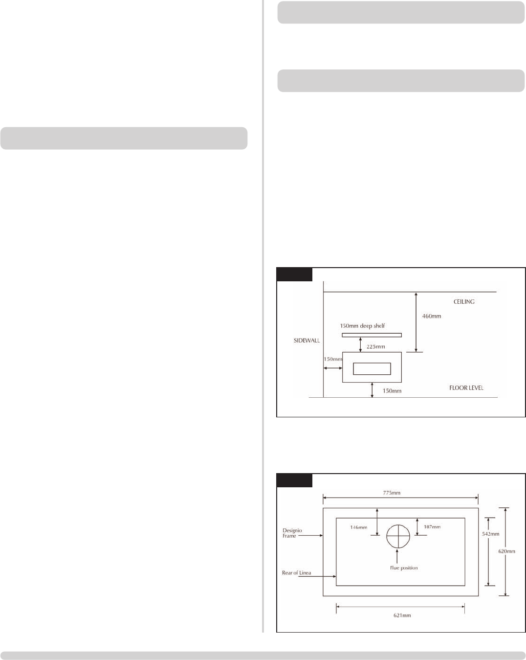
4.2 All minimum clearances must be complied with. See
diagram 3. These clearances are to the outside edge of the
decorative frame and are therefore dependant on the frame
chosen.
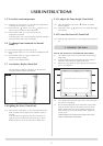
4.3 The outer dimensions of the frames and their position
relative to the flue centre and Linea are detailed in
diagrams 4 and 5.
4. APPLIANCE LOCATION
3. VENTILATION
3
AR1325
4
AR1326
DESIGNO