


24
SERVICING INSTRUCTIONS
REPLACING PARTS
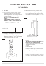
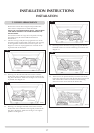
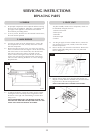
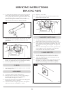
4.3 To release the right hand side of the control cover insert the
narrow blade screwdriver into the slot shown in diagram 9.
Lever it gently and pull from the right hand side at the same
time. The cover will now come off, there is a small
cylindrical metal spacer inside the cover, this must be kept
and replaced on the fixing screw during reassembly.
4.4 Disconnect the end of the ignition lead from the valve body,
see diagram 10, Arrow B, note the existing route of the
ignition lead.
4.5 Replace with a new ignition lead following the same route as
the old one. Replace the valve cover and the pilot assembly.
4.6 Check the operation of the new ignition lead.
5. PIEZO
5.1 The piezo assembly used on this appliance is not serviceable
and is unlikely to fail.
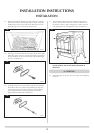
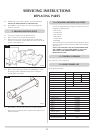
6. GAS VALVE
6.1 Turn the gas supply off at the isolation device.
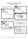
6.2 Disconnect the 2 x 8mm and 1 x 4mm gas pipe fittings at
the back of the gas valve and also disconnect the
thermocouple, see Diagram 11, Arrow A.
6.3 Remove the control valve cover and disconnect the ignition
lead from the gas valve, see section 4.
6.4 Undo the two bolts securing the gas valve to the appliance
and remove the valve, see diagram 11, Arrow C
6.5 Replace in reverse order.
6.6 Check all joints for gas leaks, check the operation of the
thermocouple and ignition lead.
7. MAGNETIC SAFETY VALVE
7.1 Turn the gas supply off at the isolation device. Undo the
thermocouple connection from the back of the gas valve.
7.2 Undo the mag valve retaining nut at the back of the control
valve, gently tap out the mag valve and replace with a new
unit. Replace the retaining nut and tighten. See diagram 11,
Arrow A.
7.3 Secure the thermocouple in the rear of the gas control. (Do
not over tighten). Turn the gas supply on and check the
entire pipework and valve joints for any leaks.
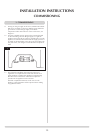
8. MAIN INJECTOR
8.1 Turn the gas supply off at the isolation device. Refer to
Section 2, Replacing Parts to remove the main burner.
8.2 Undo the compression nut from the feed pipe at the gas
control under the appliance.
8.3 Working from inside the firebox, remove the lock nut from
the injector, see diagram 12 and withdraw the injector
complete with the feed pipe from under the appliance.
AR0916
9
AR0918
12
AR0943
10
AR0943
11
B
B
C
A
C