


13
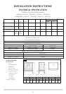
IMPORTANT: ENSURE THAT THE APPLIANCE IS
CORRECTLY ADJUSTED FOR THE GAS TYPE AND
CATEGORY APPLICABLE IN THE COUNTRY OF USE.
REFER TO DATABADGE AND TECHNICAL
SPECIFICATIONS OF THIS BOOKLET.
FOR DETAILS OF CHANGING BETWEEN GAS TYPES
REFER TO SECTION 10, REPLACING PARTS.
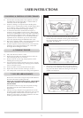
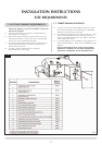
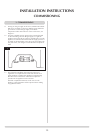
1. CONTROL UPGRADE
1.1 This stove is fitted with a control valve that can be easily
upgraded to battery powered remote control. There are two
versions of this control which can be obtained through your
local Gazco stockist.
1.2 This upgrade can be fitted before or after installation but if
side clearances are limited then it will be easier to upgrade
the stove before installation. Full instructions are included
with the kit.
1.3 STANDARD REMOTE CONTROL This remote control can
control the gas appliance after the pilot has been lit. It can
turn the main burner on and regulate it from low through to
high and back again. It can turn the main burner off leaving
the pilot burning. GAZCO PART NUMBER 8455.
1.4 THERMOSTATIC AND TIMER REMOTE CONTROL This
remote control can control the gas appliance after the pilot
has been lit. In "MANUAL MODE" it can be used to turn the
main burner on and manually regulate it from low through
to high and back again. It can also be used to turn the main
burner off leaving the pilot burning. In "AUTO MODE" it will
automatically regulate the room temperature. In "TIMER
MODE" it will turn the fire on and off according to a pre-set
programme and automatically regulate the room
temperature during two on periods. GAZCO PART NUMBER
8456.
2. SAFETY PRECAUTIONS
2.1 This appliance must be installed in accordance with the rules
in force, and used only in a sufficiently ventilated space.
Please read these instructions before installation and use of
this appliance.
2.2 These instructions, must be left intact with the user.
2.3 Do not attempt to burn rubbish on this appliance.
2.4 In your own interest, and those of safety, this appliance must
be installed by a competent person in accordance with local
and national codes of practice. Failure to install the
appliance correctly could lead to prosecution.
2.5 Keep all plastic bags away from young children.
2.6 Do not place any object on, or near to the stove. Allow
adequate clearance above the stove.
IF THE APPLAINCE IS EXTINGUISHED OR GOES OUT I N
USE, WAIT 3 MINUTES BEFORE ATTEMPTING TO
RELIGHT THE APPLIANCE.
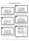
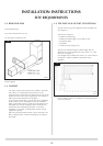
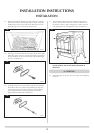
3. INSTALLATION OF THE STOVE
NOTE: THE CAST IRON DOOR IS HEAVY, TAKE EXTREME
CARE WHEN HANDLING TO AVOID DAMAGING THE
OUTER CASING.
3.1 Remove the outer sleeve and associated packaging from the
stove. The ceramic logs are located behind the door.
Remove the cast iron door using the tool provided.
Remove the box and place in a safe location.
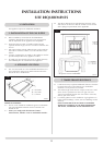
REFER TO SITE REQUIREMENTS SECTION FOR ALL FLUE
OPTIONS
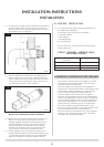
The appliance is suitable for top or rear flue exit. If a rear
flue has been purchased proceed to 3.1 below. If a top exit
is required, proceed to 3.2.
.
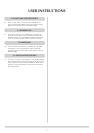
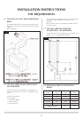
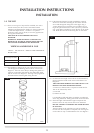
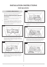
3.1 REAR EXIT FLUE
WALL THICKNESS MIN 200mm MAX 600mm
3.1.3 Remove the adjustable flue assembly and terminal guard
from the box. Take care not to lose the fixings.
3.1.4 Decide on the final stove position and ensure that all
external flue terminal clearances are complied with, See
Section 1, Site Requirements. Mark the centreline of the
appliance on the wall and mark the height from the top of
the hearth to the centre of the flue. See diagram 1.
TAKE CARE WHEN MARKING OUT FOR THE FLUE. IT IS
DIFFICULT TO MOVE AFTER INSTALLATION.
A 152mm (6") diameter hole is required to install the flue.
This can be achieved by either:
a) Core Drill.
b) Hammer & Chisel.
It is advisable to drill small holes around the circumference
when using method b). Make good at both ends of the hole.
INSTALLATION INSTRUCTIONS
INSTALLATION
1
AR0605