


10
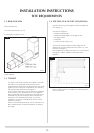
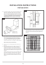
1.2 REAR FLUE 8526
Terminal dimensions:
395 x 200 x 200 mm (H x W x D)
Cut to length as required on site.
Guard Supplied.
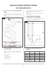
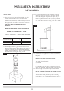
1.3 TOP EXIT
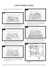
Two types of top exit flue terminal are available, horizontal
and vertical. For a horizontal terminal, decide on the
terminal position and measure the height from the top of the
appliance to the centre of the required hole. For minimum
and maximum flue dimensions see diagram 3.
Access must be either above or at the side of the installation
to allow the flue to be assembled on top of the appliance.
When a horizontal terminal is used, the vertical sections are
assembled first, then the 90-degree elbow and finally the
horizontal section including the terminal. If a masonry
installation is to be built, a suitable lintel must be used to
support the opening.
Only the horizontal terminal section can be reduced in size.
Refer to Balanced Flue Technical Information for details of
flue length.
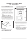
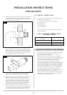
1.4 TOP FLUE UP & OUT KIT (8523/8523AN)
Vertical from the top of the appliance then horizontally out.
(See diagram 3.)
The basic kit comprises:
1 x 500mm vertical length
1 x 500mm terminal length (cut to length on site)
1 x 90 degree elbow
1 x wall plate
1 x 75mm restrictor fixing screws
The kit is the minimum required. Extra lengths may be
added to the vertical and horizontal (see section 1.5), with
reference to Diagram 3.
Extra lengths may be added (see section 1.5), with reference
to diagram 3 and the installation instructions of the
appliance.
Refer to Table A under 3.2, Installation for identifying when
to use the restrictor.
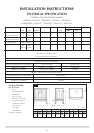
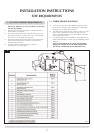
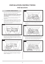
INSTALLATION INSTRUCTIONS
SITE REQUIREMENTS
2
AR0630
3
AR1619