


Magnum 6K16-Series Managed Fiber Switch Installation and User Guide (04/06)
36
www GarrettCom com
..
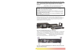
Step 1. Make sure the 6KPM Card package has all necessary accessories to install it
properly. Each 6KPM Card package except the Gigabit, for field installation
contains (Daughterboard (Bigger) and Granddaughter board (smaller), three 5/8
stand offs for Granddaughter board, 6 standoff for daughter Board, nine #4-40
Pan-Head screws along with Front panel face plate package. The Front panel
faceplate package includes 2 retainer brackets and four #2-56 flat head screws.
NOTE: Every 6KPM Card package comes with their matching Daughter and
Granddaughter board. The copper 6KPM card should not work properly if
mixed with other Fiber combo 6KPM card packages. Always install the PM
module separately one by one to avoid the mixing. Do not change the Blue
color DIP Switch setting ever, and leave it at factory default.
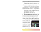
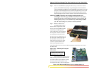
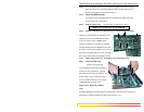
Step 2. Remove Chassis Cover
The Magnum 6K16-Series
chassis consists of top-bottom, front
and rear parts and assembled together
with the help of 18 Philips-head
screws. There are 6 screws located on
the front panel of the unit (2 each on
top and the bottom and one each at
the side), 12 for top-bottom cover of
the unit (6 each on the bottom side of
the unit) and 6 screws each on the
sides and 6 screws for the rear panel
(2 each on top and bott0m and one
each on the side). Remove these
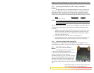
screws. Once these screws are removed, the front panel is easily slid out to the front of
the chassis base.
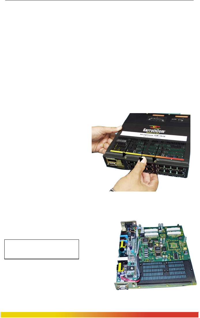
Figure 3.6.1a: Removing the Front panel
from the unit
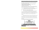
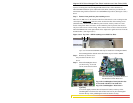
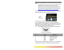
Caution: Be careful not to
disturb the power supply.
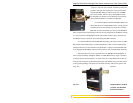
Once the front panel is removed, the
front cover may be slid out to the front of the
unit. Hold on the back part and then carefully
and slowly slide out the top chassis cover
towards the front side, as shown in the picture.
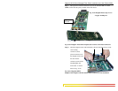
Figure 3.6.1b: Magnum 6K16-Series, Top view without chassis cover