


Magnum 6K16-Series Managed Fiber Switch Installation and User Guide (04/06)
34
www GarrettCom com
..
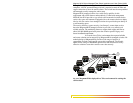
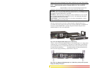
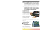
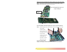
3.4 Powering the Magnum 6K16-Series Managed Fiber Switch
The Magnum 6K16-Series Switches incorporate an internal universal power
supply and have a recessed male IEC connector for the AC power cord at the left-rear. A
manual power ON-OFF switch is adjacent. A six-foot 115 VAC 60 Hz standard power
cord is supplied with each unit shipped within the United States and Canada.
The auto-ranging power supply supports installation environments where the
AC voltage is from 90 to 260 volts with a power input frequency between 47 and 63 Hz.
The 16-port units will consume over 20 watts of power typically. When connecting the
Ethernet cabling, there is no need to power down the unit. Individual cable segments can
be connected or disconnected without concern for AC power-related problems or damage
to the unit.
Power supply options are available to suit the 6K16-Series Switches to special
high-availability communications and/or heavy industrial-grade applications, including:
* -48VDC, 24VDC and 125VDC with single DC input,
* -48VDC, 24VDC and 125VDC with dual-source DC input,
See the Appendices of this manual for more details. Use an RFQ for other variations.
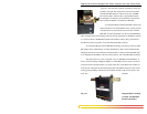
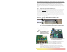
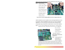
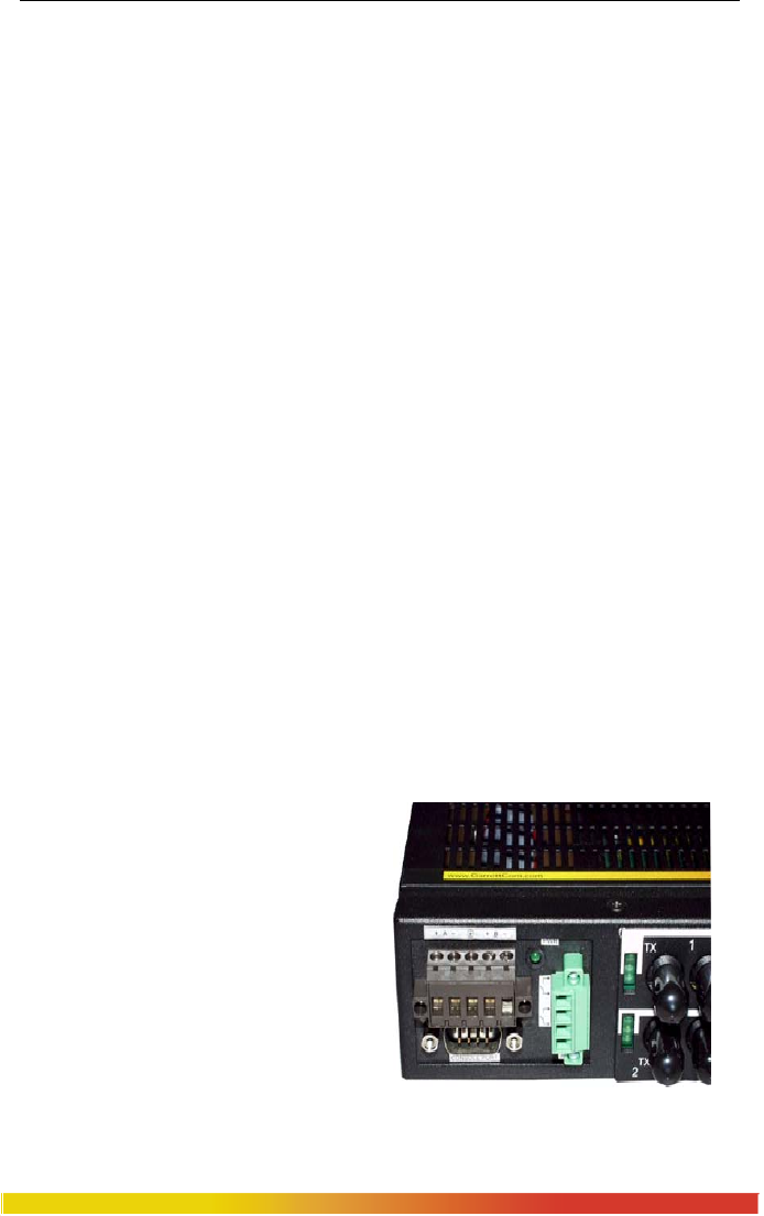
3.5 Alarm Contacts for monitoring internal power, and Software Traps
The Alarm Contacts feature, standard on Magnum 6K16-Series’s, provides
two Form C Normally Closed (NC) contacts to which the user can attach two sets of
status monitoring wires at the green terminal block. When this option is present, the
terminal block for Alarm Contacts is part of the Power Input panel in the Magnum
6K16’s case. The AC or DC power input connection is in the same panel. A manual On-
Off Switch for power to the unit is not available on 6K16 units with the Alarm Contacts
option, as these two features occupy the same space in the case.
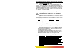
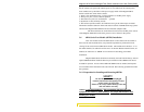
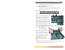
The first NC Alarm Contact (top position) is a “Software Alarm”, operated
by user settings in the MNS-6K software.
The user can disable the Software Alarm
feature with a software configuration
command if desired. When the Software
Alarm is enabled, the Form C Normally
Closed (NC) contact is held close during
normal software operation. A user-defined
software malfunction, such as an SNMP
Trap or a Software Security violation or an
S-Ring Fault, causes the contact to open
and thus trigger an alarm in the user’s
monitoring system
The second (bottom position) NC Alarm Contact is held close when there is