Page 12 Page 13
product overvIeW
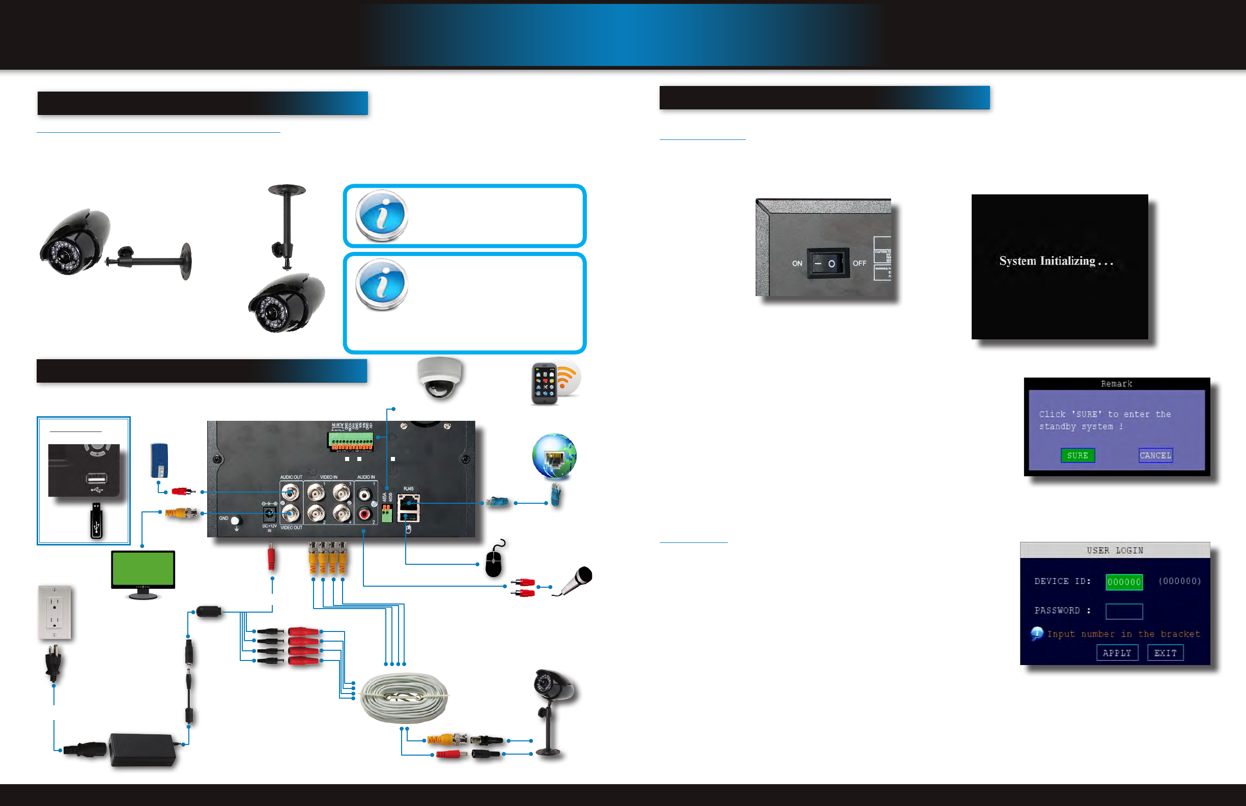
camera and power connections
InItIal setup
system operation
InstallIng cameras
Mounting Cameras and Running Cable
Select the position for the camera and secure the camera stand. Screw the camera onto the stand. Adjust camera to the proper
view angle. Make sure the lens is upright relative to the subject. Tighten the thumb bolt. First Alert cameras can be either ceiling or
wall mounted by simply reversing the camera stand mounting. See “Camera Orientation” Info box. Holes are provided on both the
bottom and top of the camera housing to accommodate most mounting requirements. Run cable from camera to DVR location. See
Information box below on “Longer Cable Runs”.
Camera Orientation
It’s important the camera is mounted correctly to
ensure the image is not upside down as the cam-
era lens can only be positioned one way.
Longer Cable Runs
Longer cable runs may require an upgrade to
RG59 Coax cable. First Alert kits ship with eco-
nomical AV cable that is designed to work well up
to the length of cable provided, usually around
60 feet. If longer distances between camera and
DVR are required, you will need to upgrade to RG59 Coax cable. We
provide several lengths up to 300 feet. In addition, if you need to run
cable for in-wall installations, then you may require fire rated cable,
FT-4/CMR UL approved for in-wall installations.
Camera - Wall Mounted
Camera - Ceiling Mounted
connectIng devIces
Splitter -
4 camera/
1 Power
Video to DVR
Video to Camera
Power to Camera
Power to Cameras
Power
from 120V
DC Converter - 12V
AV Cable: BNC/
DC Power
(1 per Camera)
BNC to Security
Camera Monitor
(Not included)
RJ45 Ethernet to
Router and Internet
PTZ and Alarm Connections
(PTZ Cameras not included)
Follow this diagram to make device connections. Note, some devices are
not included with this kit. See “What’s in the Box” for included devices.
DVR Front Face
Connect USB Drive
RCA Audio Out to
Powered Speakers
(Not included)
Smartphone through Mobile
Internet Setup
(Smartphone Not included)
USB Mouse
Power to DVR
RCA Audio In from Audio
Cameras or Powered
Microphone
(Not included)
system start up
Power On/Off
To power the system On/Off, connect the power cable to the DC 12V port on the rear panel. Flip the toggle switch on in the back
of the DVR. At startup, the system performs a basic system check and runs an initial loading sequence. After a few moments, the
system loads a live display view.
Standby Mode
The system can also be put into Standby Mode. Power will remain to the system
but will not be recording. To start/stop Standby Mode:
1. Press and hold the STANDBY button on the front panel or remote control
until the prompt closes. The system enters standby mode. You can also enter
Standby mode through the Quick Access Menu. See next page.
2. To exit standby mode, press and hold the STANDBY button on the front panel
or remote control until the system beeps. The system will begin powering up.
User Login
Password
ATTENTION: By default, passwords are disabled on the system. You do not need
to enter a password when accessing any system menus. However, for security
purposes, it is highly recommended to enable passwords on the system using the
Password Menu. See “Password” section for details on setting up passwords.
Click EXIT to cancel password setup.
Standby Mode
User Login Menu
Power Switch


