


Page 22 Page 23
advanced operatIon
alarm
advanced operatIon
alarm
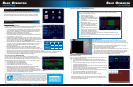
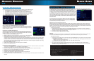
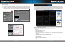
4. Use TAMPER ALARM to set the system to notify you when a camera has
been blocked by something. When a Tamper Alarm is triggered, in the Live
View Screen you will see a red【B】in the Channel with an alarm warning.
Configure the following for each channel:
• SWITCH: Turn feature ON/OFF
• SENSITIVITY: Configure LOW/MEDIUM/HIGH
5. Click APPLY. Click CLOSE in the confirmation window.
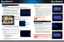
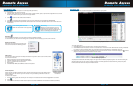
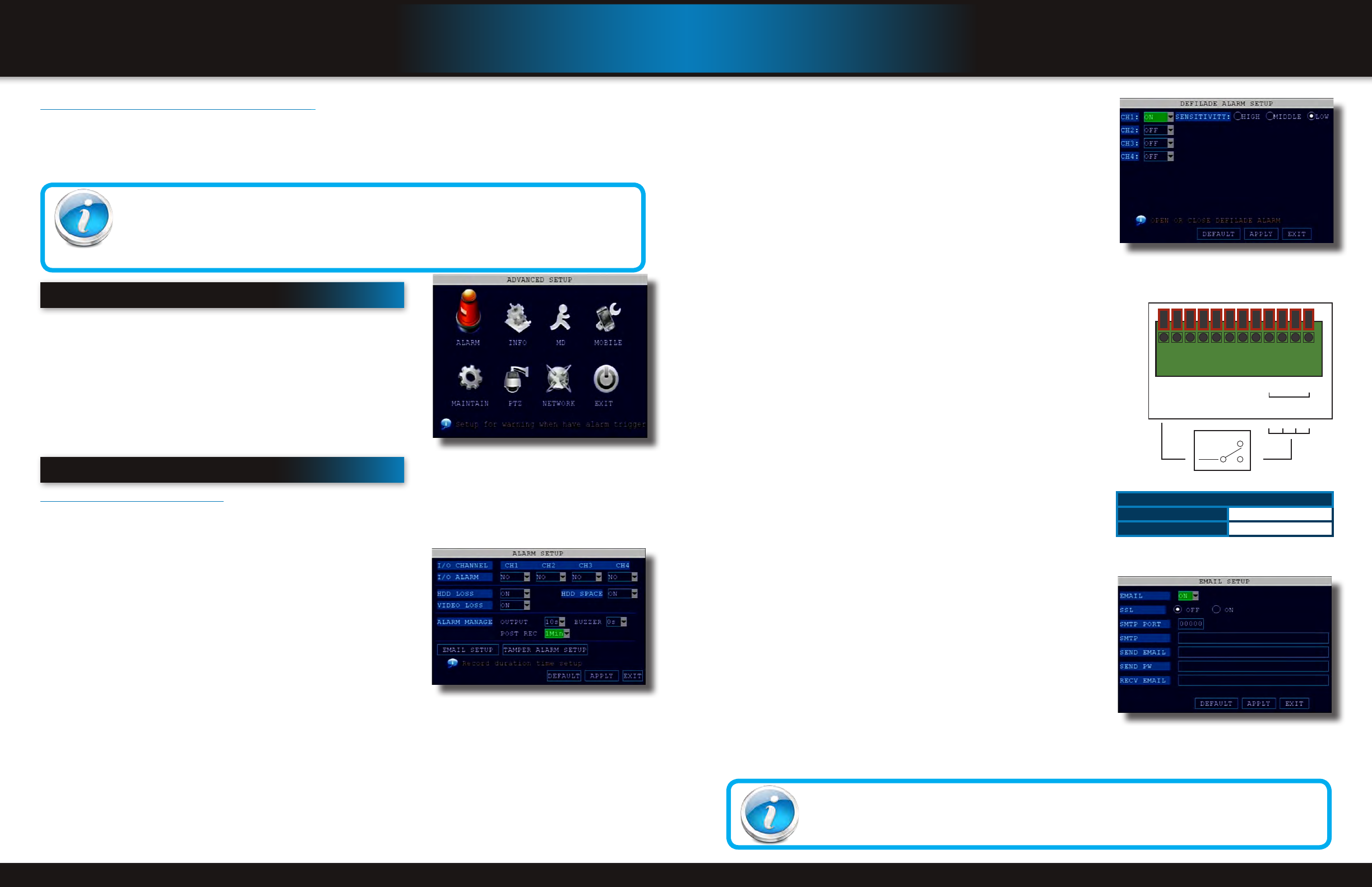
Alarm Inputs:
Alarm inputs are devices or switches that activate when a door, window,
cabinet etc. is opened or accessed. For example, you might want to only have
the camera record when someone opens a tool cabinet or when a door opens
vs. recording when motion occurs around those areas. There may be people
moving by those areas frequently but you are only concerned about when those
areas are accessed. This saves hard drive space and makes it easier to find an
event that was recorded to the hard drive.
To configure alarm inputs for devices without their own voltage you will use the
+5V input supplied on the alarm block. See Alarm Inputs Configuration diagram at
the right.
Note: If Alarm Input Device has its own power supply make sure:
1. Voltage rating is between 5V and 12V. Do not use the +5V connection on the
Alarm Block.
2. Ground must be connected to GND in Alarm Block for device to operate
properly
When an alarm is triggered, in the Live View Screen you will see a red【I】in the
Channel with an alarm input warning. You may also see a【R】if you set up the
channel to record when an alarm is triggered.
Alarm Ouput:
Alarm output is used to activate an external device such as a horn or light after an
alarm is triggered. To do this the DVR uses a dry contact normally open relay.
To configure alarm ouputs, connect the external device to the NO (Normally
Open) and COM (Common) connections on the alarm block as required by the
device. Use the ground (GND) input if required. The maximum contact rating
is 3A 24VDC.
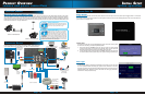
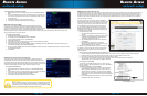
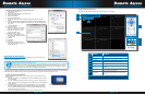
E-mail Setup:
The system can send an e-mail notification with a JPEG snapshot for triggered
events on the system. To setup e-mail notification:
1. Under EMAIL, select ON.
2. Under SSL, select OFF. NOTE: SSL deals with encryption. Only advanced
users should enable this option.
3. Under SMTP PORT, enter the SMTP port of your e-mail server.
4. Under SMTP, enter the SMTP address of your e-mail server. For example,
smtp.gmail.com
5. Under SEND EMAIL, enter the sender e-mail address.
6. Under SEND PW, enter the password of your e-mail server.
7. Under RECV EMAIL, enter the e-mail address that will receive the e-mail
notification.
8. Click APPLY. Click SURE in the confirmation window.
9. Click EXIT in all menus until all windows are closed.
Tamper Alarm Setup
E-mail Tip
Depending upon your settings, the system can generate a lot of e-mail alerts. For that reason, we recommend
setting up a dedicated e-mail address specifically for the Security System alert notices. Also to better manage
your alerts, you will want the alert e-mails to go to a different account than the one sending them.
From NO or NC depending
on setup selected to alarm
inputs 1 through 4
COM
NO
NC
Example Device:
Door Sensor
Use +5V from
Alarm Block
GND
+ 5V
N/A
N/A
GND
GND
1NO
1COM
1
4
3
2
ALM IN
Alarm Inputs Conguration
(for devices without voltage)
Note: If Alarm Input Device has its own power supply make sure:
1) Voltage rating is between 6V and 24V. The +5V input is not used
on Alarm Block.
2) Ground must be connected to GND in Alarm Block for device
to operate properly
E-mail Setup Screen
Hard Drive and USB Options continued:
Formatting the USB Flash Drive
Use a USB flash drive to backup recorded video and upgrade the system`s firmware. You should always format the USB flash
drive you intend to use with the system.
NOTE: Not formatting the USB flash drive may result in improper functionality.
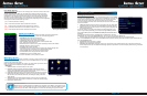
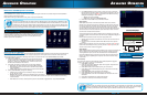
advanced setup
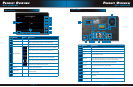
Use the ADVANCED SETUP menu to configure alarm settings, motion detection,
mobile surveillance, PTZ settings and network settings. The Advanced Setup
menu contains the following sub-menus: Alarm, Info, MD (Motion Detect),
Mobile, System, PTZ, and Network
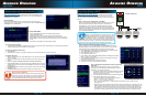
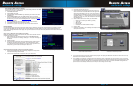
alarm
Alarm and E-mail Options:
Use the Alarm menu to configure alarm and e-mail settings. NOTE: External alarm devices must be connected to the alarm block
on the rear panel of the DVR in order to use the I/O (input/ output) alarms of the system. See next section “Alarm Inputs” and
“Alarm Inputs Diagram” for details on attaching alarm inputs. To access this menu, from the MAIN MENU click ALARM.
To configure alarm settings:
1. Under I/O CHANNEL, select NO (Normal Open), NC (Normal Closed),
or OFF for Alarm input. Alarm Input 1 on Alarm Block controls CH1 1
(Camera 1). Note: If in the RECORD screen, a Channel is set to OFF,
ALARM is also disabled for that Channel.
2. To activate Loss Alarms use drop down menu and select ON/OFF:
• HDD LOSS: The alarm will sound if the internal HDD is damaged
• HDD SPACE: The alarm will sound when the HDD is full (overwrite
must be disabled)
• VIDEO LOSS: The alarm will sound when a camera is disconnected
3. Under ALARM MANAGE, configure the following:
• OUTPUT: Set the output time (in seconds) on the spot monitor from
0s, 10s, 20s, 40s, or 60s.
• BUZZER: Set the time (in seconds) for the DVR buzzer to sound when
an alarm is triggered—0s, 10s, 20s, 40s, or 60s NOTE: Set the buzzer to 0s if you want to disable the alarm during
motion detection.
• POST REC: Set the time (in seconds) for the system to record after a triggered alarm—30s, 1MIN, 2MIN, 5MIN
Advance Setup Menu
USB Flash Drives
The system is compatible with most major brands of USB flash drives, with capacities from 256 MB to 4 GB. If
you need to reformat your flash drive then click on the USB FORMAT button while the USB drive is connected to
the USB port on the front of the DVR. Be aware that this button is not for use with any external USB hard drive
you may connect to the DVR for backup. External hard drives will need to be formatted using the FAT32 format
and this can be done by connecting the drive to the USB port on a PC and reformatting it from there.
Alarm Manage Screen
Alarm Block Voltage
Max Switching Voltage
up to 24VDC
Max Switching Current
up to 3A