


16 Installation (for qualified installers only)
Travis Industries 4050114 100-01149
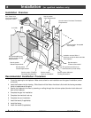
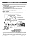
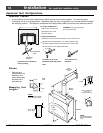
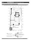
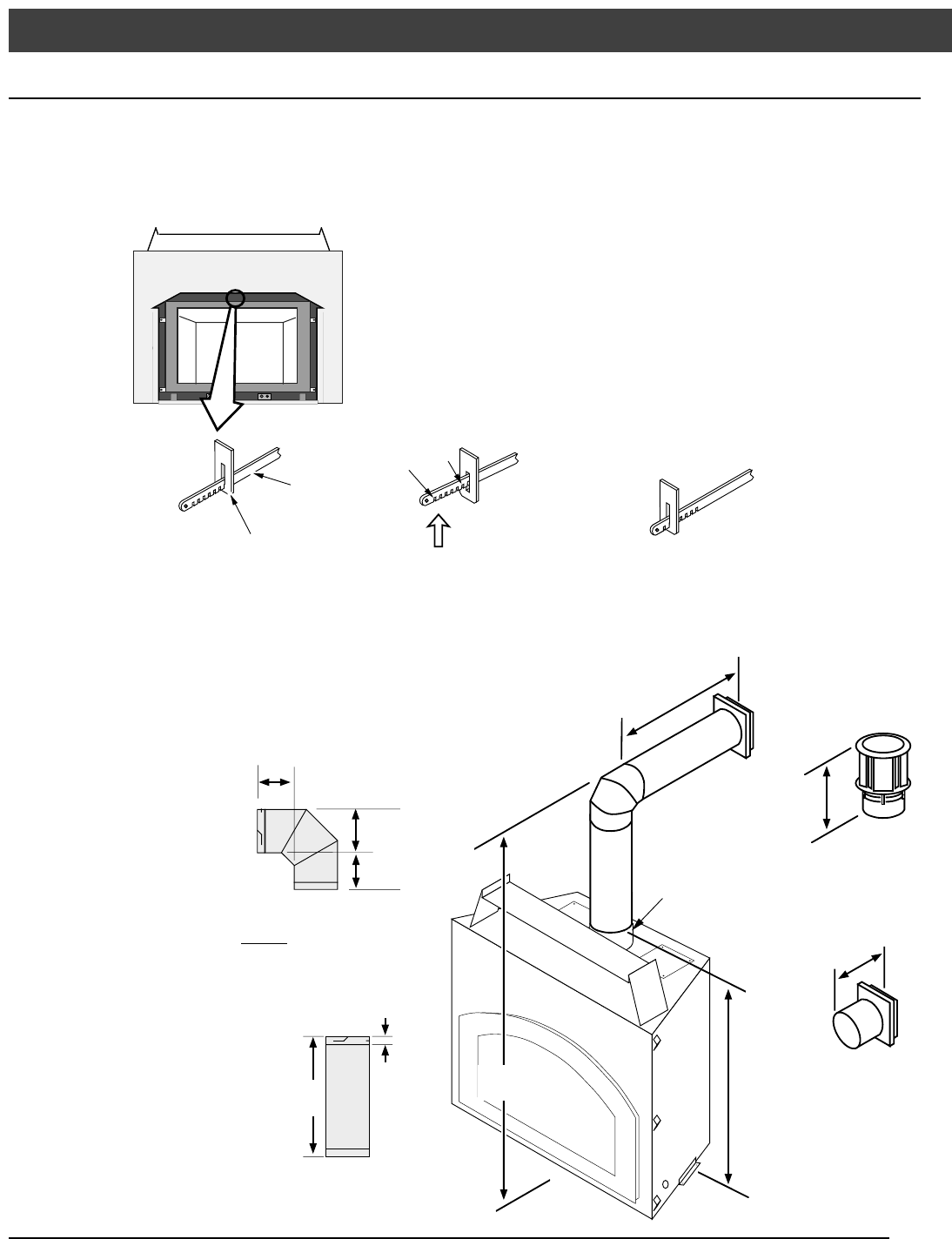
Approved Vent Configurations
Restrictor Position
• A vent restrictor is built into the appliance to adjust the flow rate of exhaust gases. This ensures proper
combustion for all vent configurations. Depending upon the vent configuration, you may be required to adjust
the restrictor position. The charts for acceptable vent configurations detail the correct vent restrictor position.
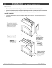
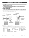
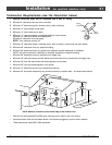
With the face removed and
the fireplace cool, reach
above the firebox.
To Adjust the Restrictor:
To Access the Restrictor:
1
2
Determine the correct restrictor position (see the charts under
"Approved Vent Configurations" - the factory position is #1).
Lift up the adjustment plate and move it so the correct notch
falls into the slot on the adjustment bracket.
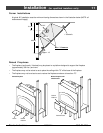
This restrictor is in position 1
(factory setting).
This restrictor is in
position 6.
Adjustment
Bracket
To adjust, lift up on the
adjustment plate and push it
back.
WARNING: Use a glove to protect
your hand from burns.
Adjustment
Plate
# 7
# 2
etc.
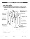
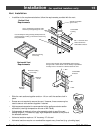
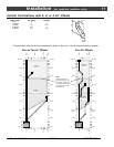
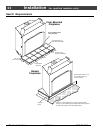
Elbows
• See the vent
configurations for
details on how
many elbows may
be used and in
what manner.
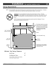
Measuring Vent
Lengths
6-1/4"
NOTE:
All measurements
are for 8" diameter
vent.
Vent
Horizontal
Run
Vent
Height
43-1/8"
10-3/4" wide with
1-3/4" to
3-3/8" of overlap
Starter
Section
12-3/8"
3-1/2"
Side
View
1-3/4"
Vent Length
(2', 3', etc.)
NOTE:
Vent sections overlap
each other by 1-3/4"
3-1/2"
8"