


30318 R4 9/9/2005
9
trunk ducts. These systems may require
modification to provide some resistance
to the airflow to prevent over-amping of
the direct drive blower motor. Selecting a
lower blower speed may correct this
problem.
Direct drive blower speeds are adjusted
by changing the "hot" wires to the motor
winding connections. Please refer to
wiring diagram in Appendix B or the
wiring diagram label affixed to the
furnace. THE NEUTRAL WIRE
(normally the white wire) IS NEVER
MOVED TO ADJUST THE BLOWER
SPEED.
DO NOT CONNECT POWER LEADS
BETWEEN MOTOR SPEEDS. THE
NEUTRAL WIRE MUST ALWAYS BE
CONNECTED TO THE MOTOR'S
DESIGNATED NEUTRAL TERMINAL.
It is possible and acceptable to use a
single blower speed for both heating and
cooling modes. The simplest method to
connect the wiring from both modes is to
use a "piggy-back connector"
accommodating both wires on a single
motor tap. It is also acceptable to
connect the selected motor speed with a
pigtail joined to both heating and cooling
speed wires with a wire nut. As a safety
precaution against accidental
disconnection of the wires by vibration, it
is advisable to secure the wire nut and
wires with a few wraps of electricians
tape.
If the joining of the blower speed
wiring is done in the furnace junction
box, tape
off both ends of the unused
wire.
DISCONNECT THE POWER SUPPLY
TO THE FURNACE BEFORE
OPENING THE BLOWER ACCESS
DOOR TO SERVICE THE AIR FILTER,
FAN AND MOTOR. FAILURE TO
SHUT OFF POWER COULD ALLOW
THE BLOWER TO START
UNEXPECTEDLY, CREATING A RISK
OF DEATH OR PERSONAL INJURY.
Do not use the blower speed wires as
a source of power to accessories as
electronic air cleaners and humidifier
transformers. The unused motor taps
auto-generate sufficiently high
voltages to damage accessory
equipment. Use the terminals
provided on the electronic fan timer.
Do not start the burner or blower fan
unless the blower access door is
securely in place.
Additional ST9103 Fan Timer Control
information is in Appendix A, Tables, and
in Appendix B, Wiring Diagrams.
HUMIDIFIER
A humidifier is an optional accessory
available through most heating supplies
outlets. Installation should be carried out
in accordance with the humidifier
manufacturer's installation instructions.
Water or water droplets from the
humidifier should not be allowed to come
into contact with the furnace heat
exchanger. Do not use direct drive motor
connections as a source of power for
120 VAC humidifiers and humidifier
transformers.
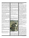
OIL BURNER
The oil burner must align properly with
the cerafelt fiber chamber (firepot). The
cerafelt fiber chamber is initially quite
soft, but hardens and becomes quite
brittle after the first firing. The firepot is
held in place by a retaining bracket;
however, it is possible for the firepot to
shift if subjected to rough handling during
transit.
BEFORE OPERATING THE
FURNACE CHECK BURNER
ALIGNMENT WITH COMBUSTION
CHAMBER. THE END CONE OF THE
AIR TUBE MUST BE CENTRED TO
THE ACCOMODATING RING
PROVIDED IN THE DESIGN OF THE
COMBUSTION CHAMBER. ADJUST
ALIGNMENT AS NECESSARY
BEFORE THE FIRST FIRING.
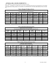
OIL BURNER NOZZLES
WML-C AND MPL-B furnaces are
certified for multiple firing rates, ranging
from approximately 58,000 to 85,600
BTU/hr. on the WML-C and 85,500 to
123,000 BTU/Hr. on the MPL-B By
changing the oil burner nozzle within the
specific model range, and temperature
rise, the furnace may be fired at an ideal
rate for a wide range of structures.
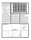
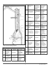
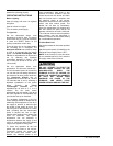
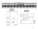
Figure 4: Horizontal Smoke Test Port Location Figure 5: Vertical Smoke Test Port Location