


30318 R4 9/9/2005
14
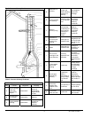
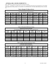
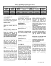
Table A-4 Riello Balanced Flue (BF) Burner Set-Up
Riello Balanced Flue Series Oil Burners
(For use with sidewall vented units using outdoor combustion air)
Furnace
Model
Output
BTU/Hr
Burner
Model
Nozzle
Pump
Pressure
Flow Rate
Turbulator
Setting
WML-60CRB 59,500 40BF3 0.50 / 60°W 105 PSIG 0.51 USGPH 1.0
WML-80CRB 75,000 40BF3 0.60 / 60°W 115 PSIG 0.65 USGPH 1.5
WML-90CRB 85,600 40BF3 0.65 / 60°W 135 PSIG 0.75 USGPH 2.0
NOTE: Air gate setting may vary for sidewall vented units where air gate must be adjusted to achieve zero smoke.
A.1 OIL BURNER AIR
ADJUSTMENT
For complete details, consult the oil
burner instruction manual provided in
the furnace documents envelope.
Beckett AF Burner
Adjust the air shutter by loosening the
locking screws and moving the air
shutter, and if necessary, the bulk air
band.
Beckett AFII Burner
Adjust the burner air supply by first
loosening the locking screw located on
the black dial to the right of the burner.
Turn the black dial clockwise to
increase the combustion air and
counter-clockwise to decrease the
combustion air. Re-tighten the locking
screw after obtaining the proper setting.
Riello 40 Series (Chimney Vented)
Riello burners are factory set with
respect to nozzle size; pump pressure,
air gate and turbulator adjustments for
each model and firing rate. By
removing the burner cover and
loosening the screws that secure the
air adjustment plate, the combustion air
can be adjusted. Move the adjusting
plate to either increase or decrease
combustion air. When the proper air
setting is achieved, retighten the fixing
screws.
Riello Balanced Flue (BF) Series
Riello burners are factory set with
respect to nozzle size; pump pressure,
and turbulator adjustments for each
model and firing rate. The combustion
air can be adjusted with the burner
cover on by first removing the plastic
cover on the top right hand side of the
burner cover. With a Philips head
screw driver, turn the adjustment screw
clockwise to increase combustion air or
counter-clockwise to decrease
combustion air. When the combustion
air is set, re-insert the plastic cover.
A.2 BURNER ELECTRODES
Adjustment of the electrode tips with
respect to each other, the nozzle, and
to the rest of the burner is very
important to ensure smooth start-ups
and to permit efficient combustion.
Beckett AF Burner
Electrode gap: 5/32 inch.
Distance above horizontal centerline:
5/16 inch. Older instruction sheets
specify 7/16 inch. The current
specification is 5/16 inch.
Distance ahead of nozzle: 1/16 inch.
“Z” dimension, the distance from the
front of the end cone (head) to the face
of the nozzle should be 1-1/8 inches. If
a ceramic head is used, the distance
from the end cone to the nozzle face is
increased to 1-3/8 inches.
Riello 40F, & BF Burners
Electrode gap: 5/32 inch.
Distance above horizontal centerline:
13/64 inch.
Distance ahead of nozzle: 5/64 to 7/64
inch.
A.3 START UP
The furnace should be operated for a
minimum of 15 minutes to reach steady
state conditions before fine tuning
combustion. The warm up time is ideal
for testing the oil pump pressure.
Drill a 1/4-inch test port in the venting
between the furnace flue outlet and
draft regulator (barometric damper).
Insert a stack thermometer and note
the flue gas temperature. The flue
gases should be within a range of
350°F to 450°F. If the flue gases are
below the range, it may be necessary
to slow down the blower fan. If the flue
gases are above the range, the blower
fan may require speeding up. Stack
temperature varies directly with the
system temperature rise. System
temperature rise is the difference
between the furnace outlet temperature
and furnace inlet temperature as
measured in the vicinity of the
connection between the plenum take-
offs and the trunk ducts
Perform a smoke spot test. The smoke
spot should not exceed No. 1 on the
Bacharach Scale.
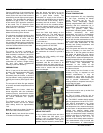
After the air adjustments have been
completed, re-check the draft pressure
at the test port on the burner mounting
plate as shown in Figure #6. The draft
should be adjusted to 0.02 inches w.c.
In the United States, the Beckett AF
Burner may be equipped with Beckett's
"Inlet Air Shut-Off" to increase
efficiency. (Beckett Part No. AF/A
5861).
NOTE: USE OF THE INLET AIR
SHUT-OFF COULD CAUSE POST
COMBUSTION NOZZLE DRIP.
A.4 SPECIAL INSTRUCTIONS
FOR UNITS EQUIPPED WITH
RIELLO BURNERS
Riello burners are factory set with
respect to nozzle size, pump pressure,
air gate and turbulator adjustments for
each model and firing rate; therefore,
do not use the above listed set up
procedures.
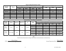
Riello specifications are listed in Tables
A-3 and A-4. Consult the Riello
Installation Instructions supplied with
the Burner for specific information
concerning burner adjustments,
operation, and trouble-shooting.