


30318 R4 9/9/2005
5
through a refrigeration unit unless the
unit is specifically approved for such
service.
Generally, a six-inch clearance between
the air conditioning evaporator coil and
the heat exchanger will provide adequate
airflow through the evaporator coil.
The blower speed must be checked and
adjusted to compensate for the pressure
drop caused by the evaporator coil.
Refer to Appendix B for recommended
wiring and electrical connections of the
air conditioning controls.
COMBUSTION AIR
When a furnace is installed in the full
basement of a typical frame or brick
house, infiltration is normally adequate to
provide air for combustion and draft
operation. If the furnace is installed in a
closet or utility room, two (2) ventilation
openings must be provided connecting to
a well ventilated space (full basement,
living room or other room opening
thereto, but not a bedroom or bathroom).
One opening shall be located 6" from the
top and bottom of the enclosure at the
front of the furnace. For furnaces located
in buildings of unusually tight
construction, such as those with high
quality weather stripping, caulking,
windows and doors, or storm sashed
windows, or where basement windows
are well sealed, a permanent opening
communicating with a well ventilated
attic or with the outdoors shall be
provided, using a duct if necessary. Size
all of the openings and associated
ductwork by the standards provided in
the latest Oil Installation Code editions;
NFPA 31 in the United States, CAN/CSA
B139 in Canada. Take all fuel burning
appliances in the area into consideration
when calculating combustion and
ventilation air requirements.
The Model CAS-2B-90E Furnace Boot
manufactured by Field Controls, Inc. may
be used with the furnace to obtain
combustion air from outdoors. Use of this
device does not alter the need for
ventilation air; however, it does provide a
good source of combustion air and is
connected to the oil burner.
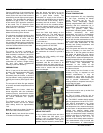
CHIMNEY VENTING
The chimney must be sized correctly and
be in good repair. If the chimney is
oversized, there is a high risk of the flue
gases condensing resulting in damage to
the chimney and other venting parts.
This problem may be corrected by the
use of an appropriately sized chimney
liner.
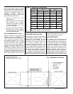
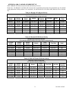
If the chimney serves the WML-C
furnace only, the vent should be sized at
5-inch minimum. The MPL-B should be
6-inch minimum. The data provided in
Table 3 is based on dedicated venting. If
the furnace is to be co-vented with other
appliances, refer to NFPA 211, Standard
for Chimneys, Fireplaces, Vents, and
Solid Fuel-Burning Appliances, NFPA
31, Standard for the Installation of Oil
Burning Equipment or CAN/CSA B139,
Installation Code For Oil Burning
Equipment for correct sizing information.
NOTE: This furnace is approved for
use with L-Vent.
NOTE: Maximum temperature for L-
Vent is 575°F (300°C).
IMPORTANT: The chimney must be
capable of providing sufficient draft at all
times for the safe removal of the
products of combustion.
The chimney should be tested under
“winter” conditions; doors and windows
closed, all other fossil fuel burning
appliances on, clothes dryer on,
bathroom fans on, etc. If the chimney
cannot overcome the competition for air,
it will be necessary to access the reason
for it, and take corrective action. If the
chimney is found to be sized correctly
and in good repair, it will probably be
necessary to re-evaluate the availability
of combustion and ventilation air, and
take corrective action.
The flue pipe should be as short as
possible with horizontal pipes sloping
upward toward the chimney at a rate of
one-quarter inch to the foot. The flue
pipe should not be smaller in cross
sectional area than the flue collar on the
furnace. The flue pipe should connect to
the chimney such that the flue pipe
extends into, and terminates flush with
the inside surface of the chimney liner.
Seal the joint between the pipe and the
lining. The chimney outlet should be at
least two feet above the highest point of
a peaked roof. All unused chimney
openings should be closed. Chimneys
must conform to local, provincial or state
codes, or in the absence of local
regulations, to the requirements of the
National Building Code.
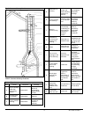
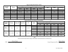
See Figure 2 and Table 2 for common
chimney problems and their remedies.
THE FURNACE MUST BE
CONNECTED TO A FLUE HAVING
SUFFICIENT DRAFT AT ALL TIMES TO
ENSURE SAFE AND PROPER
OPERATION OF THE APPLIANCE.
The flue pipe must not be routed through
concealed space, because it must be
visually checked for signs of
deterioration during the annual
inspection and servicing. The flue pipe
must not pass through any floor or
ceiling, but may pass through a wall
where suitable fire protection provisions
have been installed. In the United States,
refer to the latest edition of NFPA 31 for
regulations governing the installation of
oil burning equipment. In Canada, refer
to the latest edition of CAN/CSA B139
for rules governing the installation of oil
burning equipment.
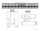
NOTE: THE RECOMMENDED FLUE
DRAFT PRESSURE IS -0.02 IN. W.C.
(AS MEASURED UPSTREAM OF THE
BAROMETRIC DRAFT REGULATOR).
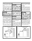
SHOWN IN FIGURE 1.
DRAFT REGULATOR CONTROL
This device is used in conjunction with
conventional chimney venting. This
control (or draft regulator) automatically
maintains a constant negative pressure
in the furnace to obtain maximum
efficiency. It ensures that proper
pressures are not exceeded. If the
chimney does not develop sufficient
draft, the draft control cannot function
properly. The draft regulator, must be
installed within the same room or
enclosure as the furnace, and should not
interfere with the combustion air supplied
to the burner. The control should be
located a minimum of 3 flue pipe
diameters from the furnace breeching
and installed in accordance to the
instructions supplied with the regulator.