


30318 R4 9/9/2005
8
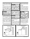
main electrical panel; however,
accessory equipment such as electronic
air cleaners and humidifiers may be
included on the furnace circuit. Although
a suitably located circuit breaker can be
used as a service switch, a separate
service switch is advisable. The service
switch is necessary if reaching the circuit
breaker involves becoming close to the
furnace, or if the furnace is located
between the circuit breaker and the
means of entry to the furnace room. The
furnace switch (service switch) should be
clearly marked, installed in an easily
accessible area between the furnace and
furnace room entry, and be located in
such a manner to reduce the likelihood
that it would be mistaken as a light
switch or similar device.
The power requirements for all models:
120 VAC, 1 ∅, 60 Hz., 12A.
Accessories requiring 120 VAC power
sources such as electronic air cleaners
and humidifier transformers may be
powered from the ST9103 EFT. Do not
use the direct drive motor connections as
a power source, since there is a high risk
of damaging the accessories by
exposure to high voltage from the auto-
generating windings of the direct drive
motor.
Thermostat wiring connections and air
conditioning contactor low voltage
connections are shown in the wiring
diagrams. Some micro-electronic
thermostats require additional controls
and wiring. Refer to the thermostat
manufacturer's instructions.
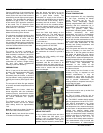
The thermostat should be located
approximately 5 feet above the floor, on
an inside wall where there is good
natural air circulation, and where the
thermostat will be exposed to average
room temperatures. Avoid locations
where the thermostat will be exposed to
cold drafts, heat from nearby lamps and
appliances, exposure to sunlight, heat
from inside wall stacks, etc.
Normal heat anticipator setting: 0.1 A.
For more precise adjustment, the heat
anticipator may be adjusted to the
amperage draw of the heating control
circuit as measured between the "R" and
"W" terminals of the thermostat. To
reduce the risk of damaging the heat
anticipator, do not measure circuit
without first removing one of the two
wires first. To determine the heating
circuit amperage draw:
1. Disconnect one of the “R” or “W”
wires from the thermostat terminal.
2. Connect an ammeter between the
wire and the thermostat terminal to
which it was attached.
3. Note the amperage reading when
the heating contacts are closed.
(System switch must be on “
HEAT” if
so equipped.
4. Re-connect the thermostat wire. If
the thermostat is serving a
combination heating and air
conditioning system, pay particular
attention to polarity.
5. When the thermostat is reconnected
and re-plumbed, adjust the heat
anticipator setting to match the
observed amperage reading.
FAN TIMER BOARD AND LIMIT
CONTROL
The Electronic Fan Timer integrates
control of all burner and circulator fan
operations. This control is the central
wiring point for most of the electrical
components in the furnace. The
Honeywell ST9103 has a fixed fan delay
on time of 30 seconds after the burner
ignites. The United Technologies 1158-
120 has an adjustable fan on time that is
set by selecting the dipswitch
combination displayed in Table 6. This
fan on delay can be set at 30, 60, 90 or
120 seconds. This provides a delay
between the burner ignition and blower
start-up to eliminate excessive flow of
cold air when the blower comes on. The
Honeywell ST9103 has an adjustable
fan off time of 60, 90, 120 and 150
seconds that is set by selecting a
dipswitch combination on the control
board displayed in Table 5. Similarly the
United Technologies 1158-120 have an
adjustable fan off time of 2, 3, 4 or 6
minutes displayed in Table 6. The fan off
delay time starts when the burner motor
is de-energized at the end of a call for
heat. Blower shutdown is delayed to
remove any residual heat from the heat
exchanger and improve the annual
efficiency of the furnace.
The electronic fan timer board works in
conjunction with snap disc limit controls,
which perform a safety function, and
breaks power to the oil burner primary
control, which shuts off the burner if the
furnace over-heats. The limit control is
thermally operated and automatically
resets. The limit control is factory
installed, pre-set and is not adjustable.
If a limit control opens, the Honeywell
ST9103 will energize the circulating fan.
When the limit control closes the burner
is re-energized and the heating cycle
begins again.
If the limit control opens with the United
Technologies 1158-120 electronic fan
control, the circulating fan will be
energized as well. When the limit closes,
the control initiates a two minute delay.
When this delay is finished, the fan off
timer will begin. At the end of the fan off
time cycle the burner will be energized,
initiating a normal burner cycle.
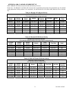
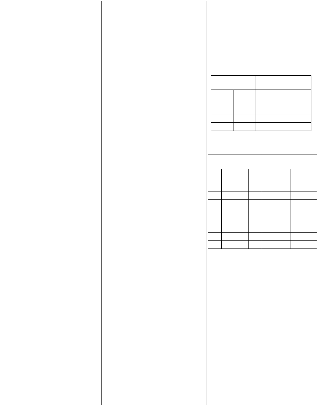
TABLE 5
Honeywell ST9103
Dip Switch
Position
Blower Off Delay
Time
1 2
On On 60 seconds
On Off 90 seconds
Off On 120 seconds
Off Off 150 seconds
TABLE 6
United Technologies 1158-120
Dip Switch
Position
Blower Delay
Times
1 2 3 4 On
Seconds
Off
Minutes
Off Off 30
On Off 60
Off On 90
On On 120
Off Off 2
On Off 3
Off On 4
On On 6
Note: It is advisable not to set the
fan on delay time for a time period
longer than 90 seconds at highest
input. Longer fan on delay times
may result in nuisance limit trips.
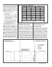
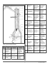
CIRCULATING AIR BLOWER
All WML-C AND MPL-B furnace models
are equipped with a direct drive blower
system. Direct drive blower speed
adjustments are not normally required in
properly sized extended plenum duct
systems. The motor RPM and air CFM
delivery will vary automatically to
accommodate conditions within the usual
range of external static pressures typical
of residential duct systems. Under-sized
duct systems may require a higher
blower speed to obtain a reasonable
system temperature rise. Some older
duct systems were not designed to
provide static pressure. They typically
feature special reducing fittings at each
branch run and lack block ends on the