


30318 R4 9/9/2005
3
IMPROPER INSTALLATION MAY
CREATE A CONDITION WHERE THE
OPERATION OF THE PRODUCT
COULD CAUSE PERSONAL INJURY
OR PROPERTY DAMAGE.
IMPROPER INSTALLATION,
ADJUSTMENT, ALTERATION,
SERVICE OR MAINTENANCE CAN
CAUSE INJURY OR PROPERTY
DAMAGE. REFER TO THIS MANUAL
FOR ASSISTANCE OR ADDITIONAL
INFORMATION, CONSULT A
QUALIFIED INSTALLER, SERVICE
AGENCY OR THE FUEL SUPPLIER.
THIS PRODUCT MUST BE INSTALLED
IN STRICT COMPLIANCE WITH THESE
INSTALLATION INSTRUCTIONS AND
ANY APPLICABLE LOCAL, STATE,
AND NATIONAL CODES INCLUDING
BUT NOT LIMITED TO: BUILDING,
ELECTRICAL AND MECHANICAL
CODES.
The furnace area must not be used as a
broom closet or for any other storage
purposes, as a fire hazard may be
created. Never store items such as the
following on, near or in contact with the
furnace:
1. Spray or aerosol cans, rags,
brooms, dust mops, vacuum
cleaners or other cleaning tools.
2. Soap powders, bleaches, waxes or
other cleaning compounds; plastic
items or containers, gasoline,
kerosene, cigarette lighter fluid, dry
cleaning fluids, or other volatile
fluids.
3. Paint thinners or other painting
materials and compounds.
4. Paper bags, boxes, or other paper
or cardboard products.
Never operate the furnace with the
blower door removed. To do so could
result in serious personal injury and/or
equipment damage.
DO NOT USE GASOLINE,
CRANKCASE OIL, OR ANY OTHER
OIL CONTAINING GASOLINE AS A
FUEL FOR THIS FURNACE.
INTRODUCTION
Please read these instructions
completely and carefully before installing
and operating the furnace.
The furnace must be installed and set up
by a qualified contractor.
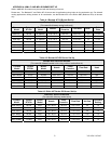
Model WML-C is an oil fired forced air
multi-positional furnace, with an output
capacity range of 58,000 BTU/Hr. to
85,600 BTU/Hr. The MPL-B is also an oil
fired forced air multi-positional furnace
with an output capacity range of 85,500
BTU/Hr. to 123,000 BTU/Hr. The WML-
C AND MPL-B furnace may be installed
in the down-flow position, as well as both
left and right horizontal positions.
All models are listed with the Canadian
Standards Association, (CSA), and
comply with the standards of both the
United States and Canada for use with
No. 1 (Stove) and No. 2 (Furnace) Oil.
In the United States, the installation of
the furnace and related equipment shall
be installed in accordance with the
regulations of NFPA No. 31, Installation
of Oil Burning Equipment, as well as in
accordance with local codes.
In Canada, the installation of the furnace
and related equipment shall be installed
in accordance with the regulations of
CAN/CSA - B139, Installation Code For
Oil Burning Equipment, as well as in
accordance with local codes.
When installation or application
questions arise, regulations prescribed in
the National Codes and Local
Regulations take precedence over the
general instructions provided with this
installation manual. When in doubt,
please consult your local authorities.
All models are shipped assembled and
pre-wired. The furnace should be
carefully inspected for damage when
being unpacked.
HEAT LOSS
To determine the correct furnace and
firing rate for an application, it is
necessary to calculate the maximum
hourly heat loss of the building based on
local design conditions. In new
construction, the heat loss should be
calculated on a room-by-room basis to
enable proper sizing of the trunk and
branch ductwork. In retrofit applications,
a building shell (overall) heat loss
calculation may be used.
In the United States, Manual J.
titled,
"Load Calculation
" published by the Air
Conditioning Contractors of America,
(ACCA), describes a suitable procedure
for calculating the maximum hourly heat
loss.
In Canada, the maximum hourly heat
loss may be calculated in accordance
with the procedures described in the
manuals of the Heating, Refrigeration
and Air Conditioning Institute (HRAI), or
by other method prescribed by
authorities having jurisdiction that are
suitable for local conditions.
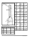
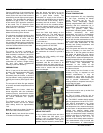
LOCATION OF UNIT
The furnace should be located such that
the flue connection to the chimney is
short, direct and consists of as few
elbows as possible. When possible, the
unit should be centralized with respect to
the supply and return air ductwork. A
central location minimizes the trunk duct
sizing. All models may be installed on
combustible floors. Do not install the
furnace on carpet or tiled floors.
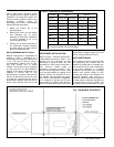
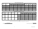
Minimum installation clearances are
listed in Table 1.
NOTE: The recommended installation
clearances do not necessarily take into
consideration the clearances necessary
to replace the air filter or perform other
routine maintenance.
DOWN-FLOW INSTALLATION
All WML-C AND MPL-B furnace models
have been assembled for installation in
the down-flow position. Maintain all
clearances to combustibles as outlined in
Table 1. Suggestion; as a measure to
prevent fuel oil from accumulating in
locations other than the fire pot, as could
be the case in the event of nozzle drip,
install the furnace with an approximate 2
degree slope from the oil burner casing
towards the fire pot. Use shims made of
noncombustible material.