


30318 R4 9/9/2005
7
OPTIONAL SIDE WALL VENTING
Certain WML-C AND MPL-B furnace
models are manufactured to be installed
as sidewall vented units. Please refer to
Direct Venting Instructions, P/N 28888
included with the Vent Kit for details.
Sidewall Venting (Direct Venting)
requires the use of specific oil burners;
the Beckett AFII, or the Riello 40BF.
Please refer to Appendix A, Tables A2,
and A4.
Note: Sidewall venting requires special
attention to combustion air supply. There
is no natural draft in the venting system
between furnace cycles; therefore, if the
indoor pressure is negative relative to
the outdoors, the vent terminal becomes
a point of infiltration. This could lead to
oil odour control problems. This problem
is rectified by the use of ducted outdoor
air for combustion (semi-sealed
combustion), using the Beckett AFII or
Riello 40BF oil burner. See Direct Vent
Instructions supplied with the Vent Kits.
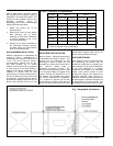
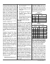
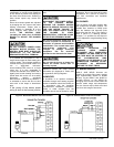
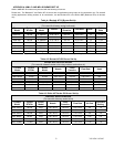
Table 3: Minimum Chimney Base
Temperatures (°F)
Chimney Height (ft.)
Nozzle
11 20 28 36
Chimney Thermal Resistance < R6
0.50 300 400 535 725
0.65 275 340 430 535
0.70 270 330 405 505
0.75 260 320 380 475
0.85 250 300 355 430
1.00 225 300 365 430
Chimney Height (ft.)
Nozzle
11 20 28 36
Chimney Thermal Resistance > R6
0.50 185 200 220 250
0.65 175 185 205 220
0.70 175 185 195 215
0.75 175 185 195 210
0.85 165 185 195 205
1.00 165 185 195 205
< - less than, > - greater than
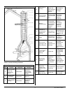
OIL TANK
Oil storage tanks must be selected and
installed in compliance with applicable
codes; in the United States, NFPA 31,
Standard for the Installation of Oil
Burning Equipment, Chapter 2. and in
Canada, CAN/CSA-B139, Installation
Code for Oil Burning Equipment, Section
6. Observe all local codes and by-laws.
In general, the oil tank must be properly
supported and remain stable in both
empty and full condition. The oil tank
must be fitted with vent and supply pipes
to the outdoors. Refer to the above-
mentioned codes for sizing. The vent
pipe must be no less than 1¼ inches
I.P.S., and terminate with an appropriate
vent cap in a location where it will not be
blocked. The fill pipe must be no less
than 2 inches I.P.S., and terminate with
an appropriate cap in a location where
debris will not enter the fill pipe during oil
delivery.
If located indoors, the tank should
normally be in the lowest level, (cellar,
basement, etc.). It must be equipped
with a shut-off valve at the tank outlet
used for the oil supply. The oil tank must
be located as to not block the furnace /
room exit pathway. Observe all
clearances specified in the above-
mentioned codes.
PIPING INSTALLATION
In the United States, NFPA 31, Standard
for the Installation of Oil Burning
Equipment, Chapter 2.
In Canada, the entire fuel system should
be installed in accordance with the
requirements of CAN/CSA B139, and
local regulations. Use only approved fuel
oil tanks piping, fittings and oil filters.
Ensure that all fittings used in a copper
oil line system are high quality flare
fittings. Do not use compression fittings.
Do not use Teflon tape on any fittings.
Pressurized or gravity feed installations
must not exceed 3 PSIG. Pressures
greater than 10 PSIG may cause
damage to the shaft seal. If the height of
the oil stored in a tank above the oil
burner exceeds 11½ feet, it may be
necessary to use a pressure-regulating
device approved for this purpose.
The furnace may be installed with a one-
pipe system with gravity feed or lift. The
maximum allowable lift on a single line
system is 8 feet. Lift should be measured
from the bottom (outlet) of the tank, to
the inlet of the burner. Sizing a single
line system is complex because of the
difficulty estimating the pressure drop
through each fitting, bend and
component in the line. In general, keep
single line systems short as possible.
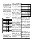
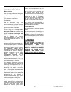
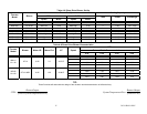
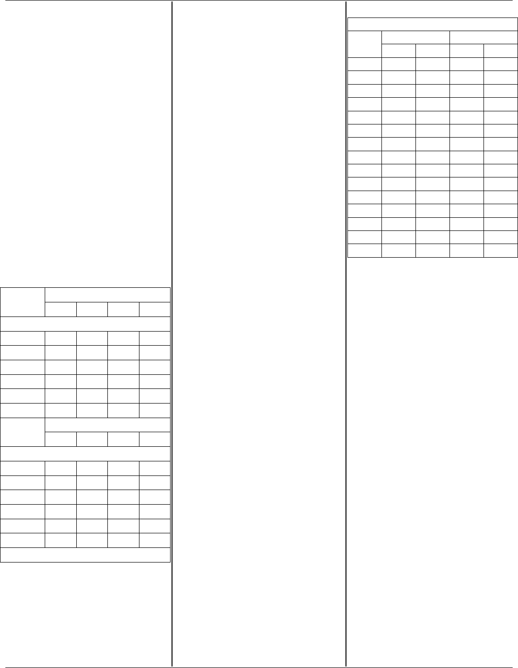
The following chart shows the allowable
line lengths (horizontal + vertical) for
single and two-line oil piping systems. All
distances are in feet.
Table 4: Oil Lines
Copper Tubing Oil Line Length (Feet)
Single-Pipe OD Two-Pipe OD
Lift
(Feet)
3/8” 1/2” 3/8” 1/2”
0 53 100 68 100
1 49 100 65 100
2 45 100 63 100
3 41 100 60 100
4 37 100 58 100
5 33 100 55 100
6 29 100 53 100
7 25 99 50 100
8 21 83 48 100
9 17 68 45 100
10 13 52 42 100
12 - - - - - - 37 100
14 - - - - - - 32 100
16 - - - - - - 27 100
18 - - - - - - 22 88
In retrofit applications, where an existing
oil line system is in place, a vacuum
check will help determine the efficacy of
the existing oil line system The vacuum
in a system should not exceed 6” Hg. for
a single pipe system, nor 12” Hg. for a
two-pipe system.
NOTE: The oil burner requires the use of
a bypass plug when converting from
single-pipe to two-pipe oil piping
systems. See burner manufacturer’s
instructions.
All fuel systems should include an oil
filter between the fuel oil storage tank
and the oil burner. For best results,
install the oil filter as close to the burner
as possible. When using an indoor oil
tank, the oil filter may be installed at the
tank downstream from the shut-off valve.
If firing the furnace under the 0.65 gph
rate, a 7 to 10 micron line filter should be
installed as close to the oil burner as
possible.
ELECTRICAL CONNECTIONS
The furnace is listed by the Canadian
Standards Association (CSA). It is
factory wired and requires minimal field
wiring. In the United States, the wiring
must be in accordance with the National
Fire Protection Association NFPA-70,
National Electrical Code, and with local
codes and regulations. In Canada, all
field wiring should conform to CAN/CSA
C22.1 Canadian Electrical Code, Part 1,
and by local codes, where they prevail.
The furnace should be wired to a
separate and dedicated circuit in the