


30318 R4 9/9/2005
15
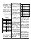
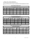
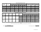
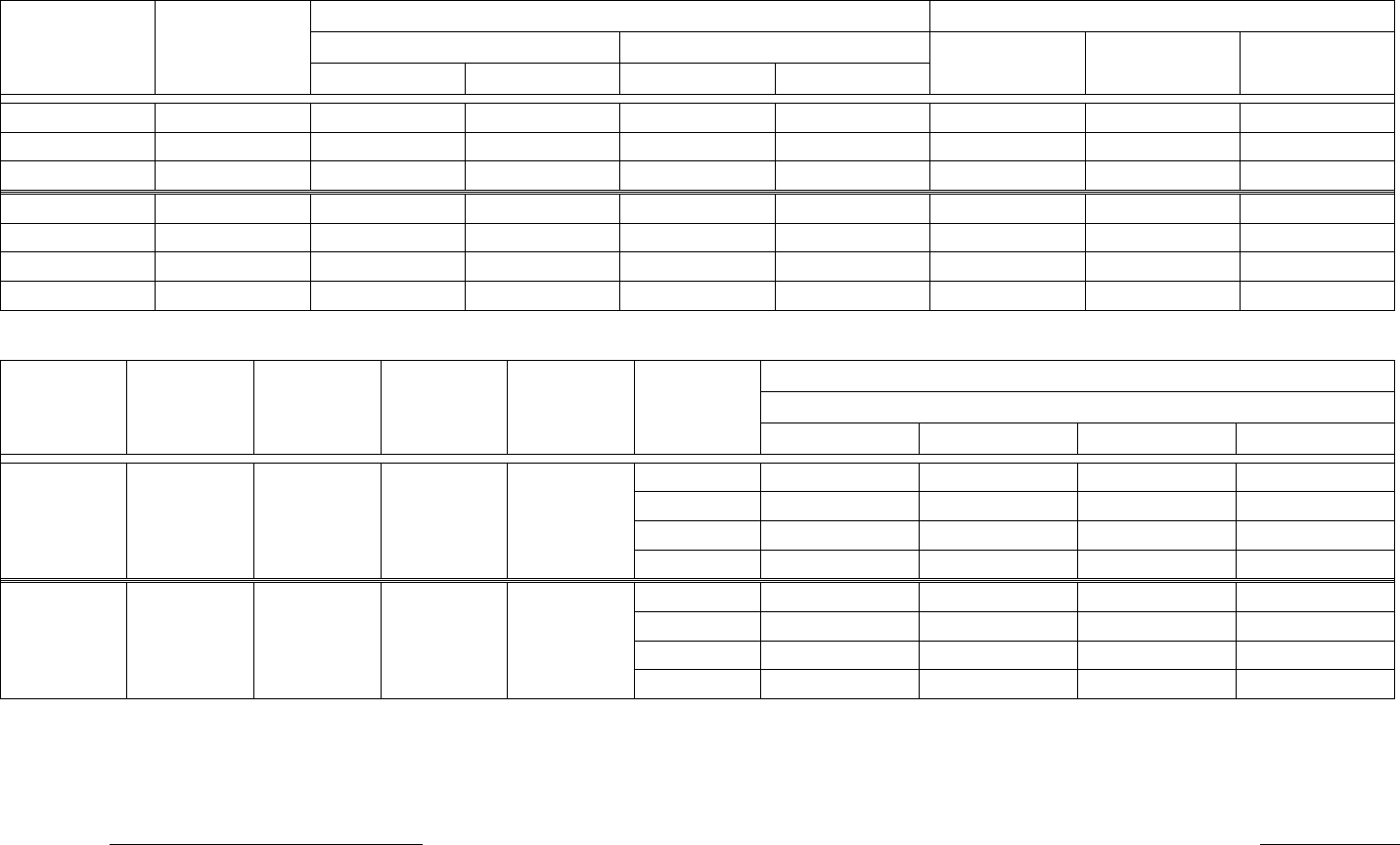
Table A-6 Direct Drive Blower Set-Up
Blower Set-Up Cooling Capacity
0.20 in. w.c. 0.50 in. w.c.
Furnace
Model
Blower
Speed Motor Speed Motor
Tons Power CFM Range
WML-60C GT10 DD Low ½ HP Med-Low ½ HP 3 ½ HP 763 – 1505
WML-80C GT10 DD Med-Low ½ HP Med-High ½ HP 3 ½ HP 763 – 1505
WML-90C GT10 DD Med-High ½ HP High ½ HP 3 ½ HP 763 – 1505
MPL-90B GT12-10DD Low ¾ HP Med-High ¾ HP
3
¾ HP 1185 – 1553
MPL-100B GT12-10DD Med-High ¾ HP High ¾ HP
3
¾ HP 1185 – 1553
MPL-120B GT12-10DD High ¾ HP High ¾ HP
3
¾ HP 1185 – 1553
MPL-130B GT12-10DD High ¾ HP High ¾ HP
3
¾ HP 1185 – 1553
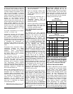
Table A-8 Direct Drive Blower Characteristics
CFM
External Static Pressure – Inches w.c.
Furnace
Model
Blower Motor HP Motor FLA ∆T Speed
0.20 0.30 0.40 0.50
LOW
813 813 797 763
MED-LOW
1170 1144 1118 1063
MED-HIGH
1423 1381 1291 1220
WML-C
60 - 90
GT10 ½ HP 7.0 45-75°F
HIGH
1505 1444 1359 1291
LOW
1334 1286 1239 1185
MED-LOW
1389 1332 1287 1236
MED-HIGH
1423 1373 1326 1289
MPL-B
90-130
GT12-10DD ¾ HP 12.5 50-80°F
HIGH
1553 1491 1449 1331
TIP:
These Formulae will assist with the design of the ductwork and the determination of airflow delivery:
() ()
CFM
Bonnet Output
x SystemTemperatureRise
SystemTemperature Rise
Bonnet Output
xCFM
= =
1085 1085. .