


30318 R4 9/9/2005
10
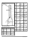
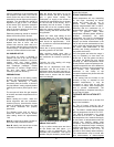
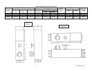
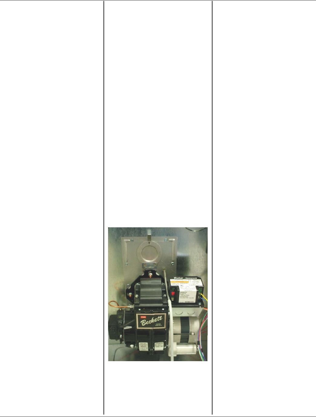
BURNER ELECTRODES
Correct positioning of the electrode tips
with respect to each other, to the fuel oil
nozzle, and to the rest of the burners is
essential for smooth light ups and proper
operation. The electrode tips should be
adjusted to a gap of 5/32”, 1/16” ahead
of the nozzle, 5/16” above the centerline
of the nozzle. The “Z” dimension (front
edge of the burner head to the front face
of the nozzle is 1-1/8 inches.
Electrode positioning should be checked
before the first firing of the furnace.
The electrode porcelains should be free
of cracks, the electrode tips should be
tapered and free of burrs, and the
contact rods must be clean and be in
firm contact with the ignition transformer
contact springs. The electrodes must not
come into contact with the burner head.
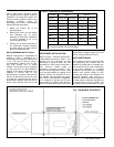
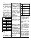
OIL BURNER SET-UP
The burner air supply is adjusted to
maintain the fuel to air ratio to obtain
ideal combustion conditions. A lack of air
causes "soft" and "sooty" flames,
resulting in soot build-up throughout the
heat exchanger passages. Excess
combustion air causes a bright roaring
fire and high stack temperatures
resulting in poor fuel efficiency.
PREPARATIONS:
Drill a ¼” test port in the venting, ideally
at least 2 flue pipe diameters away from
the furnace breeching, if venting
horizontally from the furnace, or from the
flue pipe elbow if venting vertically before
reaching the furnace. (See Figures 4 and
5).
The test port will allow flue gas samples
to be taken and stack temperatures to be
measured.
Before starting the burner, check the
burner alignment with the combustion
chamber (fire pot), check that the correct
nozzle is tightened into place, and that
the burner electrodes are properly
positioned.
The Beckett burner bulk air band is
should be closed, and the air shutter
initial setting should be approximately
7.00.
Note A: Locate hole at least 6 inches on
the furnace side of the draft control.
Note B: Ideally, hole should be at least
12 inches from breeching or elbow.
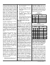
PROCEDURE:
Start the burner and allow it to run at
least ten minutes. Set the air shutter to
give a good flame visually. The
combustion air supply to the burner is
controlled by manipulating the air shutter
on the left side of the burner, and, if
necessary, the bulk air band. To adjust,
loosen the bolt on the movable shutter.
Move the shutter gradually until a good
flame (visually) has been achieved. Re-
snug the bolt.
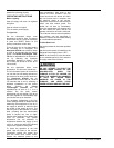
Check the initial draft setting as the
furnace warms up. The draft may be
measured at the test port. The breech
draft should be approximately - 0.05”
w.c. to obtain an over fire draft reading of
- 0.02 inches w.c.
Check the oil pump pressure. Standard
operating pressure is 100 PSIG.
After reaching steady state, take a
smoke test. If not indicating a trace, set
the combustion air controls to provide a
trace.
Typically, the CO
2
reading will range
from 11.5% to 13.5%.
After the air adjustments have been
completed, and the air shutter or air
adjustment plate has been secured, re-
check the over fire draft and take another
smoke test to ensure that the values
have not changed.
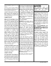
Figure 6: Checking Over-Fire Draft.
SMOKE TEST NOTE:
If oily or yellow smoke spots are found
on the smoke test filter paper, it is
usually a sign of unburned fuel. This
indicates poor combustion. This type of
problem may be caused by excess draft,
excess air, or contaminated fuel. Do not
ignore this indicator.
STACK TEMPERATURE:
Stack temperature will vary depending
on fuel input, circulating air blower
speed, and burner set up, etc. In
general, stack temperature should
typically range between 380°F to 550°F,
assuming that the combustion air is
approximately room temperature (65°F -
70°F). In general, lower stack
temperature indicates greater efficiency;
however, excessively low stack
temperature can lead to condensation
forming in the chimney and / or venting.
Sulphur and similar contaminants in the
fuel oil will mix with condensation to form
acids. Acids and resultant chemical salts
will cause rapid deterioration of the
chimney and venting components, and
may attack the furnace.
If the flue gases are below the range, it
may be necessary to slow down the
blower fan. If the flue gases are above
the range, the blower fan may require
speeding up. Stack temperature varies
directly with the system temperature rise.
System temperature rise is the difference
between the furnace outlet temperature
and furnace inlet temperature as
measured in the vicinity of the
connection between the plenum take-offs
and the trunk ducts.
If the venting from the furnace to the
chimney is long, or exposed to cold
ambient temperatures, it may be
necessary to use L-Vent as the vent
connector to reduce stack temperature
loss to prevent condensation. The
venting should be inspected annually to
ensure that it is intact.
FURNACE INSTALLATION SET-
UP
The furnace must be set up as the final
step in the installation.
A) The oil burner must be set up
following the procedures outlined above.
B) The WML-C models should operate
within a temperature rise of 45°F to 75°F.
The MPL-B temperature rise range
should be 50°F to 80°F. To determine
the temperature rise, measure the supply
air and return air temperatures when the
furnace has reached steady state
conditions. This is the point at which the
supply air temperature stops increasing
relative to the return air temperature. The
furnace may have to run 10 to 15
minutes to reach steady state conditions.
The measurements may be made with
duct thermometers or thermocouples