


30318 R4 9/9/2005
4
HORIZONTAL INSTALLATION
WML-C AND MPL-B furnaces models
are assembled and shipped ready for
installation in the down-flow position. The
furnace may be installed in either of the
horizontal positions; warm air
discharging left or warm air-discharging
right by following these steps:
1. Rotate the furnace 90° to the
desired position.
2. Remove the three nut and washer
sets fastening the oil burner
assembly to the furnace. Rotate the
oil burner assembly to be in the
normal upright position.
3. Re-align the oil burner assembly to
the combustion chamber (fire-pot),
and then secure into place with the
three nut and washer sets.
NON-SUSPENDED INSTALLATION
Maintain clearances to combustibles as
outlined in Table 1. Installation on a
combustible floor requires a clearance of
1 inch. This can be done by using a
noncombustible material such as one-
inch thick channel iron or similar
material. The furnace must be supported
in such a way as to not allow twisting or
sagging of the cabinet. Suggestion; as a
measure to prevent fuel oil from
accumulating in locations other than the
fire pot, as could be the case in the event
of nozzle drip, install the furnace with an
approximate 2-degree slope from the oil
burner casing towards the fire pot. Use
shims made of noncombustible material.
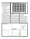
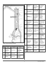
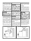
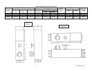
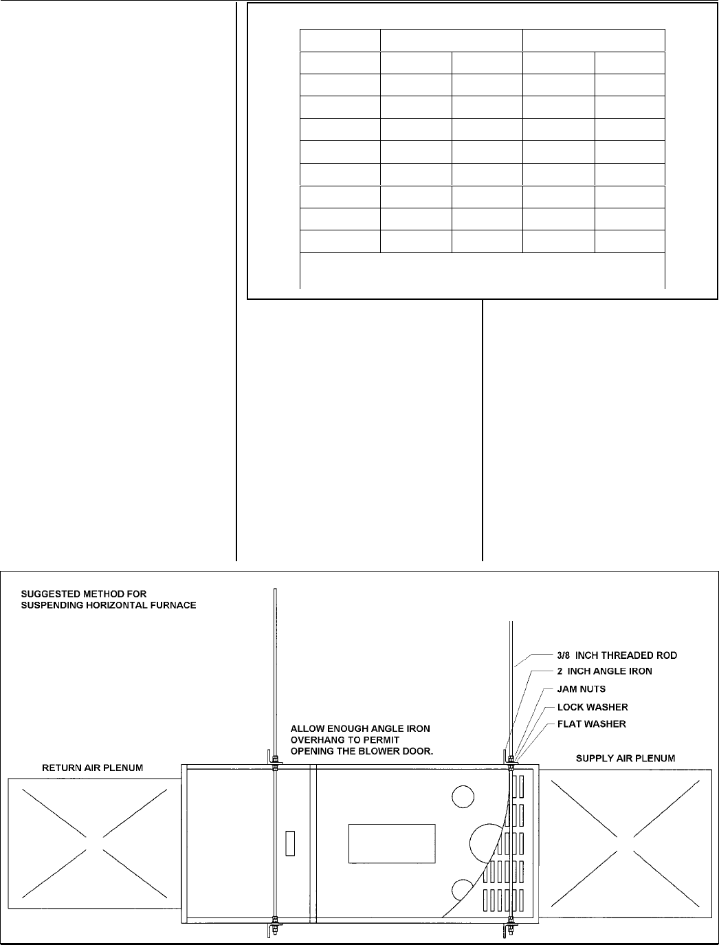
SUSPENDED INSTALLATION
Refer to Figure 1. Maintain clearances to
combustibles as outlined in Table 1. The
furnace may be suspended by field
fabricating a cradle of angle iron and
threaded rod. Secure the furnace with 2
inch minimum slotted angle or
equivalent, as shown in Figure 1. The
furnace must be supported in such a way
as to not allow twisting or sagging of the
cabinet. Position the supports so as to
not interfere with accessing the burner
and blower compartments. Suggestion;
as a measure to prevent fuel oil from
accumulating in locations other than the
fire pot, as could be the case in the event
of nozzle drip, install the furnace with an
approximate 2 degree slope from the oil
burner casing towards the fire pot.
AIR CONDITIONING
If the furnace is used in conjunction with
air conditioning, the furnace shall be
installed in parallel with or upstream from
the evaporator coil to avoid condensation
in the heat exchanger. In a parallel
installation, the dampers or air controlling
means must prevent chilled air from
entering the furnace. If the dampers are
manually operated, there must be a
means of control to prevent the operation
of either system unless the dampers are
in the full heat or full cool position. The
air heated by the furnace shall not pass
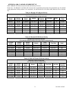
Table 1: Clearance to Combustibles
Furnace
WML-C MPL-B
Location Down flow Horizontal Down flow Horizontal
Top 0 in. 3 in. 0 in. 3 in.
Bottom 1 in. 1 in. 1 in. 1 in.
S/A Plenum 1 in. 1 in. 1 in. 1 in.
Rear 1 in. 1 in. 1 in. 1 in.
Sides 1 in. 1 in. 1 in. 1 in.
Front 10 in.
1
10 in.
1
10 in.
1
10 in.
1
Flue Pipe 9 in.
2
9 in.
2
9 in.
2
9 in.
2
Enclosure Closet Closet Closet Closet
1
24 inches is required for servicing.
2
18 inches required in the United States.
Fig 1 Suspended Installation