


035-17233-000-C-0702
8 Unitary Products
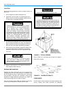
COMBUSTION DISCHARGE
The products of combustion are discharged horizontally
through two screened (hooded) openings on the upper gas
heat access panel.
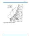
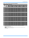
GAS PIPING
Proper sizing of gas piping depends on the cubic feet per
hour of gas flow required, specific gravity of the gas and the
length of run. National Fuel Gas Code Z223.1 should be fol-
lowed in all cases unless superseded by local codes or gas
utility requirements. Refer to Table 5.
The heating value of the gas may differ with locality. The
value should be checked with the local gas utility.
NOTE:
There may be a local gas utility requirement specify-
ing a minimum diameter for gas piping. All units require a 1
inch pipe connection at the entrance fitting.
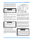
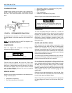
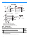
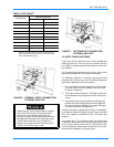
GAS CONNECTION
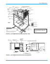
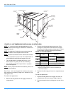
The gas supply line can be routed through the knockouts
located on the front of the unit or through the opening pro-
videdintheunit'sbase.RefertoFigure10tolocatethese
access openings.
Typical supply piping arrangements are shown in Figures 6
and 7. All shaded items are field-supplied.
Two grommets are shipped in the blower compartment (in
parts bag taped to the blower housing) of every unit with gas
heat and should be used in the knockouts when the gas pip-
ing penetrates the front of the unit.
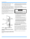
After the gas supply piping has been installed, the bottom
opening in the unit should be sealed to prevent water from
leaking into the building.
Gas piping recommendations:
1. A drip leg and a ground joint union must be installed in
the gas piping.
2. When required by local codes, a manual shut-off valve
may have to be installed outside of the unit.
3. Use wrought iron or steel pipe for all gas lines. Pipe dope
should be applied sparingly to male threads only.
4. All piping should be cleaned of dirt and scale by ham-
mering on the outside of the pipe and blowing out the
loose dirt and scale. Before initial start-up, be sure that
all of the gas lines external to the unit have been purged
of air.
5. The gas supply should be a separate line and installed in
accordance with all safety codes as prescribed under
Limitations. After the gas connections have been com-
pleted, open the main shut-off valve admitting normal
gas pressure to the mains. Check all joints for leaks with
soap solution or other material suitable for the purpose.
NEVER USE A FLAME.
6. The furnace and its individual manual shut-off valve must
be disconnected from the gas supply piping system dur-
ing any pressure testing of that system at test pressures
in excess of 1/2 psig (3.48kPa).
The furnace must be isolated from the gas supply piping
system by closing its individual manual shut-off valve
during any pressure testing of the gas supply piping sys-
tem at test pressures equal to or less than 1/2 psig
(3.48kPa).
7. A 1/8 inch NPT plugged tapping, accessible for test gage
connection, must be installed immediately upstream of
the gas supply connection to the furnace.
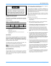
When connecting electrical power and control wir-
ing to the unit, waterproof type connectors MUST
BE USED so that water or moisture cannot be
drawn into the unit during normal operation. The
above waterproofing conditions will also apply
when installing a field-supplied disconnect switch.
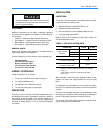
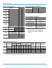
TABLE 3: CONTROL WIRE SIZES
1
1
Total wire length is from unit to room thermostat, and
back to unit.
Wire Size
2
2
Solid, Class II copper wire.
22 20 19 18 16
40 120 150 190 305
Max. Wire Length
3
Feet
3
Total Wire length is from unit to room thermostat, and
back to unit.