


035-17233-000-C-0702
Unitary Products 11
Check all connections for leaks when piping is completed,
using a soap solution. NEVER USE A FLAME.
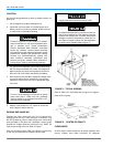
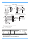
VENT AND COMBUSTION AIR HOODS
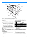
Two vent hoods and a combustion air hood (with screens) are
shipped attached to the blower housing in the blower com-
partment. These hoods must be installed to assure proper
unit function. All hoods must be fastened to the outside of the
gas heat access panel with the screws provided in the bag
also attached to the blower housing.
The screen for the combustion air intake hood is secured as
shown on the label attached to the hood. The top flange of
this hood slips in under the top of the access panel opening
when installing. Refer to Figure 8.
Each vent hood is installed by inserting the top flange of the
hood into the slotted opening in the access panel and secur-
ing in place.
OPTIONAL ECONOMIZER/MOTORIZED DAMPER
RAIN HOOD
The instruction for the optional economizer/motorized
damper rain hood can be found in form 44-320-2. Use these
instructions when field assembling an economizer rain hood
onto a unit.
The outdoor and return air dampers, the damper actuator, the
damper linkage, the outdoor and return air divider baffles,
and all the control sensors are factory mounted as part of the
Factory installed economizer option.
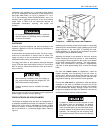
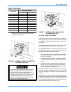
ENTHALPY SET POINT ADJUSTMENT
Remove the economizer access panel from the unit to check
the following adjustments. Loosen but do not remove the two
panel latches.
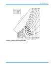
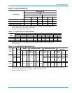
1. The enthalpy set point may now be set by selecting the
desired setpoint shown in Figure 9. Adjust as follows:
• For a single enthalpy operation, carefully turn the set
point adjusting screw to the A, B, C or D setting corre-
sponding to the lettered curve.
• For a dual enthalpy operation, carefully turn the set point
adjusting screw fully clockwise past the D setting.
2. To check that the damper blades move smoothly without
binding, carefully turn the minimum position adjusting
screw fully clockwise and then energize and de-energize
terminals R to G. With terminals R to G energized, turn
the minimum position screw counterclockwise until the
desired minimum position has been attained.
3. Replace the economizer access panel. Reposition the
two latches horizontally and retighten the screws.
POWER EXHAUST/BAROMETRIC RELIEF DAMPER
AND RAIN HOOD OPTION
The instructions for the power exhaust/barometric relief
damper and rain hood can be found in form 44-320-10. The
exhaust fan, all supporting brackets, angles, and the wiring
are factory installed as part of the power exhaust option.
All of the components, including the dampers, hardware, and
mounting instructions are shipped in a single package exter-
nal from the unit. The hood must be field assembled and
installed.
Power exhaust is not available as a field installed option.
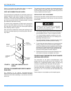
FIGURE 8 : VENT AND COMBUSTION AIR
HOODS
VENT AIR
OUTLET
HOODS
SLOTTED
OPENINGS IN
ACCESS PANEL
COMBUSTION
A
IR INTAKE
HOOD
GAS HEAT
ACCESS
PANELS
Extreme care must be exercised in turning both
the setpoint and minimum position adjusting
screws to prevent twisting them off.