


035-17233-000-C-0702
Unitary Products 19
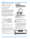
OPERATION
COOLING SYSTEM
The cooling section is a complete factory package utilizing an
air-cooled condenser. The system is factory-charged with
Refrigerant-22.
The compressors are hermetically sealed, internally sprung
and base-mounted with rubber-insulated hold-down bolts.
Compressors have inherent (internal) protection. If there is an
abnormal temperature rise in a compressor, the protector will
open to shut down the compressor.
PRELIMINARY OPERATION COOLING
After installation has been completed, energize the crank-
case heaters for at least four hours before operating the unit.
After the initial installation, the compressors should be given
three false starts (energized just long enough to make a few
revolutions) with 5-7 minutes delay between each start,
before being put into full time service.
NOTE:
Prior to each cooling season, the crankcase heaters
must be energized at least 8 hours before system is put into
operation.
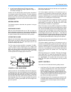
COOLING SEQUENCE OF OPERATION
NO OUTDOOR AIR OPTIONS
When the room thermostat calls for first-stage cooling, the
low voltage control circuit from R to G and Y1 is completed to
energize compressor #1, condenser fan motor #1, condenser
fan motor #2 (if the ambient temperature is above 60F), and
the supply air blower motor (if the fan switch on the room
thermostat is set in the AUTO position).
When the thermostat calls for second-stage cooling, the low
voltage control circuit from R to Y2 is completed to energize
compressor #2.
After the thermostat is satisfied and opens, all components
will stop simultaneously. The blower motor will continue to
operate if the fan switch on the room thermostat is set in the
ON position.
ECONOMIZER WITH SINGLE ENTHALPY SENSOR
When the room thermostat calls for first-stage cooling, the
low voltage control circuit from R to G and Y1 is completed.
The R to G circuit energizes the blower motor (if the fan
switch on the room thermostat is set in the AUTO position)
and drives the economizer dampers from fully closed to their
minimum position. If the enthalpy of the outdoor air is below
the setpoint of the enthalpy controller (previously
determined), Y1 energizes the economizer. The dampers will
modulate to maintain a constant supply air temperature as
monitored by the discharge air sensor. If the outdoor air
enthalpy is above the setpoint, Y1 energizes compressor #1,
condenser fan motor #1, and condenser fan motor #2 (if the
ambient temperature is above 60°F).
When the thermostat calls for second-stage cooling, the low
voltage control circuit from R to Y2 is completed. If the
enthalpy of the outdoor air is below the setpoint of the
enthalpy controller (i.e. first stage has energized the econo-
mizer), Y2 will energize compressor #1. If the outdoor air is
above the setpoint, Y2 will energize compressor #2.
After the thermostat is satisfied and opens, all components
will stop simultaneously. The blower motor will continue to
operate if the fan switch on the room thermostat is set in the
ON position.
ECONOMIZER WITH DUAL ENTHALPY SENSORS
The operation with the dual enthalpy sensors is identical to
the single sensor except that a second enthalpy sensor is
mounted in the return air. This return air sensor allows the
economizer to choose between outdoor air and return air,
whichever has the lowest enthalpy value, to provide maxi-
mum operating efficiency.
ECONOMIZER (SINGLE OR DUAL) WITH POWER
EXHAUST
This system operates as specified above with one addition.
The power exhaust motor is energized whenever the econo-
mizer is chosen by the enthalpy sensor for first stage cooling,
Y1. As always, the R to G connection provides minimum
position but does not provide power exhaust operation.
MOTORIZED OUTDOOR AIR DAMPERS
This system operation is the same as the units with no out-
door air options with one exception. When the R to G circuit is
complete,themotorizeddamperdrivesopentoapositionset
by the thumbwheel on the damper motor. When the R to G
circuit is opened, the damper spring returns fully closed.
CONTINUOUS BLOWER
Continuous blower operation is possible by closing the R to G
circuit on the thermostat.
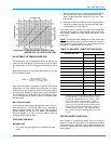
SAFETY CONTROLS
1. A Suction Line Freezestat to protect against low evapo-
rator temperatures due to a low air flow or a low return
air temperature. (Opens at 26°F + 5°F and resets at 38°F
+ 5°F)
2. A High Pressure Cutout Switch to protect against exces-
sive discharge pressures due to a blocked condenser
coil or a condenser motor failure. (Opens at 380 psig +
10 and resets at 300 psig +10)