


035-17233-000-C-0702
Unitary Products 15
NOTE: A 1” clearance must be provided between any com-
bustible material and the supply air ductwork for a distance of
3 feet from the unit.
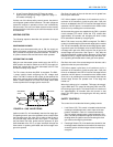
NOTE:
The products of combustion must not be allowed to
accumulate within a confined space and recirculate.
NOTE:
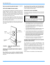
Locate unit so that the vent air outlet hood is at least:
• Three (3) feet above any force air inlet located within 10
horizontal feet (excluding those integral to the unit).
• Four (4) feet below, 4 horizontal feet from, or 1 foot
above any door or gravity air inlet into the building.
• Four (4) feet from electric and gas meters, regulators
and relief equipment
NOTE:
All entry holes should be field sealed to prevent rain
water entry into building
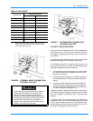
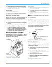
Duct Covers - Units are shipped with the bottom duct open-
ings covered. An accessory flange kit is available for con-
nectingsideducts.
For bottom duct applications:
1. Remove the side panels from the supply and return air
compartments.
2. Remove and discard the bottom duct covers. (Duct
openings are closed with sheet metal covers except
when the unit includes a power exhaust option. The cov-
ering consists of a heavy black paper composition.)
3. Replace the side supply and return air compartment pan-
els.
For side duct applications:
1. Replace the side panels on the supply and return air
compartments with the accessory flange kit panels.
2. Connect ductwork to the duct flanges on the rear of the
unit.
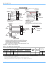
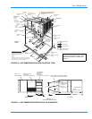
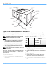
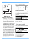
FIGURE 12 : UNIT DIMENSIONS DHE/DHG180 & 240 (REAR VIEW)
R E T U R N
A I R
O U T D O O R
A I R
S U P P L Y
A I R
G A U G E L I N E
A C C E S S
C O M P R E S S O R
A C C E S S
S U P P L Y A I R
A C C E S S
C O N D E N S E R S E C T I O N
R E T U R N A I R
A C C E S S
O U T D O O R A I R
C O M P A R T M E N T
A C C E S S
1 " N P T F E M A L E
C O N D . D R A I N
C O N N E C T I O N
F I L T E R
A C C E S S
D O T P L U G
( F o r p r e s s u r e
d r o p r e a d i n g )
E V A P O R A T O R
S E C T I O N
4 0 - 1 / 2 "
2 8 - 5 / 8 " ( 1 5 T o n s )
3 9 - 5 / 8 " ( 2 0 T o n s )
2 7 - 3 / 4 "
5 - 1 / 8 "
1 8 - 5 / 8 "
5 - 1 / 2 "
4 0 - 3 / 8 "
R E A R
V I E W
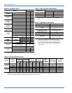
TABLE 10: UTILITIES ENTRY
HOLE
OPENING SIZE
(DIA.)
USED FOR
A
1-1/8” KO
Control Wiring
Front
3/4” NPS (Fem.) Bottom
B
3-5/8” KO
Power Wiring
Front
3” NPS (Fem.) Bottom
C
2-3/8” KO
Gas Piping (Front)
1
1
1” Gas Piping MPT Required.
D
1-11/16” Hole
Gas Pipping (Bottom)
1,
2
2
Opening in the bottom to the unit can be located by the
side in the insulation.