


035-17233-000-C-0702
22 Unitary Products
5. Set room thermostat to desired temperature.(If thermo-
stat set temperature is above room temperature, pilot
burner ignition will occur and, after an interval to prove
pilot flame, main burners will ignite).
TO SHUT DOWN:
1. Turn off electric power to unit.
2. Depress knob of gas valve while turning to off position.
POST-START CHECK LIST (GAS)
After the entire control circuit has been energized and the
heating section is operating, make the following checks:
1. Check for gas leaks in the unit piping as well as the sup-
ply piping.
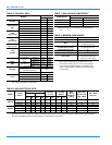
2. Check for correct manifold gas pressures. See Checking
Gas Input.
3. Check the supply gas pressure. It must be within the lim-
its shown on rating nameplate. Supply pressure should
be checked with all gas appliances in the building at full
fire. At no time should the standby gas line pressure
exceed 13", nor the operating pressure drop below 5.0"
for natural gas units. If gas pressure is outside these lim-
its, contact the local gas utility for corrective action.
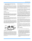
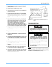
MANIFOLD GAS PRESSURE ADJUSTMENT
Small adjustments to the high-fire gas flow may be made by
turning the pressure regulator adjusting screw on the auto-
matic gas valve. Refer to Figure 16.
Adjust as follows:
1. Remove the cap on the regulator. It's located next to the
push-on electrical terminals.
2. To decrease the gas pressure, turn the adjusting screw
counterclockwise.
3. To increase the gas pressure, turn the adjusting screw
clockwise.
NOTE:
The correct manifold pressure for these furnaces is
3.5 IWG 0.3.
PILOT CHECKOUT
The pilot flame should envelope the end of the flame sensor.
Refer to Figure 16. To adjust pilot flame, (1) remove pilot
adjustment cover screw, (2) increase or decrease the clear-
ance for air to the desired level, (3) be sure to replace cover
screw after adjustment to prevent possible gas leakage.
Put the system into operation and observe through complete
cycle to be sure all controls function properly.
BURNER INSTRUCTIONS
To check or change burners, pilot or orifices, CLOSE MAIN
MANUAL SHUT-OFF VALVE AND SHUT OFF ALL ELEC-
TRIC POWER TO THE UNIT.
1. Remove the screws holding either end of the manifold to
the burner supports.
2. Open the union fitting in the gas supply line just
upstream of the unit gas valve and downstream from the
main manual shut-off valve.
3. Remove the gas piping closure panel.
4. Disconnect wiring to the gas valves and spark ignitors.
Remove the manifold-burner gas valve assembly by lift-
ing up and pulling back.
Burners are now accessible for service.
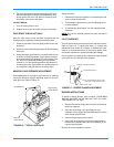
FIGURE 16 : TYPICAL GAS VALVE
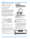
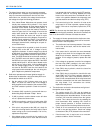
FIGURE 17 : PROPER FLAME ADJUSTMENT
1 / 8 " G A P B E T W E E N C A R R Y - O V E R
T U B E A N D F L A M E S E N S O R B U L B
C A R R Y - O V E R T U B E
F L A M E S E N S O R B U L B
B U R N E R A S S E M B L Y B R A C K E T
On-Off Control
Pilot Adj.
(Under Screw)
High Fire Adj.
(Under Screw)