


Subject to change without notice. Printed in U.S.A.
Copyright © by Unitary Products 2002. All rights reserved. Supersedes: 035-17233-000 Rev B (0500) 035-17233-000-C-0702
Unitary 5005 Norman
Products York OK
Group Drive 73069
d. If the furnace is cold, check for 24 volts at wire 241
attached to the time delay relay (ETD) located in the
main control box. If 24 volts is not found, replace the
ETD relay.
e. If 24 volts is found at wire 241, remove the wires
attachedtothe(ETD)andwithaVOM,checkfor
continuity across contacts 1 and 2. If none is found,
the (ETD) is open and must be replaced. If there is
continuity, re-attach the wires.With the draft motor
running, check for 24 volts at terminal 4 of (RW1-2)
and (RW2-1). If 24 volts is not present, the centrifu-
gal switch (CS) has not closed or has gone bad.
Check the line voltage to the unit - if it is correct,
replace the draft motor. If line voltage is low, call the
power company.
f. Check for 24V at terminal 2 of (RW1-2 and RW2-1).
If 24V is not present, check for 24V at (RW1 and
RW2) relay coils. If these relays are pulled in, then
check for a loose connection at terminal 2 and termi-
nal 4 of each relay. If no problem is found, then
replace (RW1 and/or RW2) as required.
g. If 24 volts is present at the ignitor controls, check all
control wiring at the ignitor controls and the high ten-
sion wire to the ignitors. Check that the ground wires
from the ignitor controls, the gas valves and pilot
burners are all intact and making good electrical
connection. Check to make sure that the ceramic
insulator on the pilot ignitors or sensors is not bro-
ken or cracked, if all are intact, replace the ignition
control IC1 or IC2.
5. The draft motor runs and the sparker sparks at the pilot
burner but the pilot does not ignite and a gas odor is not
detected at the draft motor outlet.
a. Check to make sure gas is being supplied to the
unit. Make sure that the gas pressure to the unit is
within the proper limits as described in the POST
START CHECK LIST and that the pilot adjust screw
is allowing some flow of gas as described in PILOT
CHECKOUT.
b. Check all wiring between the ignitor control and the
gas valve. Check to make sure the ground connec-
tions are intact.
c. If the wiring is intact, check for 24 volts across termi-
nals PV and COMMON on the ignitor control. If 24
volts is not present, replace the ignitor control.
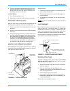
d. If 24 volts is present, remove the pilot burner and
remove the pilot orifice from the pilot burner. The ori-
fice is removed in the direction opposite the flow of
gas. Inspect the orifice for obstruction. If it is clear,
replace the main gas valve.
6. The sparker sparks at the pilot burner but the pilot does
not ignite and a gas odor is detected at the draft motor
outlet.
a. Adjust the pilot adjust screw on the gas valve as
described in PILOT CHECKOUT.
b. Check the supply pressure as described in POST
START CHECK LIST. Make adjustments as neces-
sary.
c. Check the pilot orifice for obstruction as described in
para. 5d. Clean as needed but the problem should
not be the gas valve.
7. The pilot burner ignites but the sparker continues to
spark and the main burners do not ignite.
a. Make the same checks and adjustment as
described in para. 6.
b. Make sure that the pilot burner is not bent or dam-
aged.
c. Make sure that the ground connections at the pilot
burner, gas valve and ignitor control are intact.
Check the high tension wire for good electrical con-
nection. If all are intact, replace the ignitor module.
8. The pilot burner lights and the spark stops but the main
burners do not light.
a. Check electrical connections between the ignitor
control and the gas valve. If intact, check for 24 volts
across terminals MV and COMMON terminals. If no
voltage detected, replace ignitor control. If voltage is
present, replace gas valve.
9. Furnace lights with roll-out or one burner has delayed
ignition.
a. Make sure that the pilot burner is aligned properly
with the carryover as described in PILOT CHECK-
OUT.
b. Make sure that the carry overs on adjoining burners
are screwed fast and are level with respect to one
another.
10. Main burners light but exhibit erratic flame characteris-
tics.
a. Adjust air shutters as described in BURNER AIR
SHUTTER ADJUSTMENT.
b. Check the main burner orifices for obstruction and
alignment. Removal procedure is described in
BURNER INSTRUCTIONS. Clean or replace burner
orifices and burners as needed.