


035-17233-000-C-0702
Unitary Products 21
3. Redundant Gas Valve - There are two separate gas
valves in the furnace. Each valve contains a main and a
redundant valve. The redundant valves are located
upstream of the main gas valves. Should either or both
of the main gas valves fail in the open position the redun-
dant valves serve as back-ups and shuts off the flow of
gas.
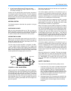
4. Flame Sensor Rod / 100% Ignition Control Lock-Out -
The flame rods and controls are located per Figure 15. If
an ignition control fails to detect a signal from the flame
sensor indicating the pilot flame is properly ignited, then
the main gas valve will not open. It will continue to try
and ignite the pilot for a maximum of 85 seconds, then if
the pilot flame is not detected, the ignition control will
lock out furnace operation until 24V power is removed
from the module either at the unit or by resetting the
room thermostat.
5. Rollout Switch - This switch is located above the main
burners in the control compartment which in the event of
a sustained main burner rollout shuts off and locks out
both ignition controls closing both gas valves. The igni-
tion controls lock out furnace operation until 24V power
is removed from the controls either at the unit or by
resetting the room thermostat. Note the auto reset rollout
switch must reset before allowing furnace operation.
6. Auxiliary limit switch (AUX) - This control is located
inside the heat exchanger compartment and is set to
open at 190F. It is a manual reset switch. If AUX limit
trips, then the primary limit has not functioned correctly.
Replace the primary limit switch.
HEAT ANTICIPATOR SETPOINTS
It is important that the anticipator setpoint be correct. Too
high of a setting will result in longer heat cycles and a greater
temperature swing in the conditioned space. Reducing the
value below the correct setpoint will give shorter ON cycles
and may result in the lowering of the temperature within the
conditioned space.
START UP
PRE-START CHECK LIST
Complete the following checks before starting the unit.
1. Check the type of gas being supplied. Be sure that it is
the same as listed on the unit nameplate.
2. Make sure that the vent and combustion air hoods have
been properly installed.
OPERATING INSTRUCTIONS
TO LIGHT PILOT AND MAIN BURNERS:
1. Turn off electric power to unit.
2. Turn room thermostat to lowest setting.
3. Turn gas valve knob to on position.
4. Turn on electric power to unit.
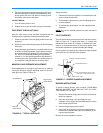
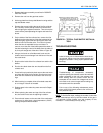
FIGURE 15 : GAS VALVE AND CONTROLS
I G N . C O N T R O L # 1
I G N . C O N T R O L # 2
I G N I T O R # 1
G V 1
G A S
V A L V E
G V 2
G A S
V A L V E
I G N I T O R # 2
S E N S O R # 2
S E N S O R # 1
R O L L O U T S W .
B U R N E R C O M P A R T M E N T
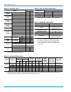
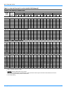
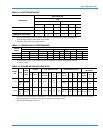
TABLE 16: LIMIT CONTROL SETTING
Units
(Tons)
Capacity, MBH
Limit
Control
Opens, °F
Input Output
15 & 20 300 240 195
15 & 20 400 320 195
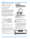
TABLE 17: HEAT ANTICIPATOR SETPOINT
Gas Valve 1st Stage 2nd Stage
Honeywell VR8440
0.30 amp 0.11 amp
White-Rodgers 36C68
This furnace is equipped with an intermittent pilot
and automatic re-ignition system. DO NOT attempt
to manually light the pilot.