


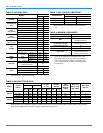
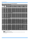

035-17233-000-C-0702
Unitary Products 27
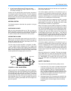
1. The indoor blower motor is a non-inherently protected
three-phase motor. Protection is provided by an overload
relay for overcurrent and fuses for short circuit. If the
motor fails to run, check the line voltage circuit and con-
trol voltage circuit per the following procedure:
a. If the Indoor Blower Motor does not operate, check
visually that contactor M3 is pulled in. If so, check
for line voltage between all three phases at the line
terminals of the Blower Overload Relay (BOR). If
line voltage is found, check the leads to the blower
motor for open circuit. If line voltage is found at the
motor leads (inside the conduit box on the motor
shell), disconnect the motor and check for open
windings per the motor wiring diagram. If open wind-
ings are found, replace the motor. If line voltage is
not found at the BOR, trace the leads back to the
field supply terminal block, checking for an open cir-
cuit or blown fuses.
b. If the contactor M3 is not pulled in, check for control
voltage (24V) at the M3 coil. If voltage is found,
replace the contactor. If control voltage is not found
at M3, check for voltage across terminals 95 & 96 of
the BOR. If voltage exists, the BOR is open on over-
load. The BOR should be set to the auto reset posi-
tion. The BOR must cool down in order to reset. If
theBORwillnotreset,replacetheBOR.IftheBOR
resets and M3 pulls in, but the indoor blower motor
will still not run, refer to para. (a) for troubleshooting
the line voltage supply circuit. If control voltage is
not found at the BOR, trace the circuit back to the
relay board and thermostat per the unit wiring dia-
gram. Replace any defective components.
2. Draft motor operates and furnace lights but supply air
blower does not start after a short time delay with room
thermostat fan switch set to AUTO.
a. Set fan switch to ON. If blower motor runs, go to
Step f. If it does not, check to see if line voltage is
being supplied to the contacts of the contactor (M3),
and if the contactor is pulled in. Check for loose wir-
ing.
b. If contactor (M3) is pulled in, proceed with the trou-
bleshooting steps indicated in Step 1 above.
c. If (M3) is pulled in and the blower motor still does
not run, replace the blower motor.
d. If (M3) is not pulled in, check for 24 volts at the (M3)
coil. If 24 volts is present, replace the (M3) contac-
tor.
e. If 24 volts is not present at the (M3) coil, check for
loose 24 volt wiring back to the relay board. Check
control wiring to the room thermostat. If all is fine,
replace the relay board.
f. If the blower motor runs with the fan switch in the
ON position but does not run soon after the furnace
has ignited with the fan switch in the AUTO position,
check for loose 24 volt wiring between the relay
board in the main control box, the Mate-N-Lok con-
nector in the partition between the evaporator and
gas heat sections and the time delay relay (ETD).
g. If all control wiring is fine, check for 24 volts at the
relay board. If 24 volts is present, replace the relay
board. If 24 volts is not present, replace the (ETD)
relay.
NOTE:
The furnace may shut itself down on a high tempera-
ture condition during the procedure, but this will not effect the
test if it is done within 5 minutes of furnace shut-down.
3. The supply air blower operates but the draft motor does
not when the room thermostat is set to call for heat and
the fan switch in the ON position.
a. The draft motor has inherent protection. If the motor
shell is hot to the touch, wait for the internal over-
load to reset.
b. If the motor shell is cold with the room thermostat
calling for heat, check for line voltage at the motor's
Mate-N-Lok connector attached to the evaporator
partition. If line voltage is present, replace the draft
motor.
c. If line voltage is not present, check for line voltage at
the heat relay (RW1) contacts in the main control
box and check to see if the (RW1) is pulled in.
d. If the (RW1) relay is pulled in, check for a loose line
voltage connection.
e. If the (RW1) relay is not pulled in, check for 24 volts
at the (RW1) coil. If 24 volts is present, replace the
(RW1) relay. If 24 volts is not present, check for a
loose 24 volt connection back to the relay board and
check the connections from the room thermostat to
the relay board. If all connections are correct,
replace the relay board.
4. The draft motor runs but the furnace does not light and
the sparker does not spark.
a. The ignition control (IC1, IC2) may be locked out
due to either a flame roll out or 100% shut off. These
safety features are described above. If lock-out has
occurred, 24V must be removed from the ignition
controls. This is done at the unit or by resetting the
room thermostat. After resetting 24V, check for
proper furnace operation. If lock-out continues to
occur, locate the source of the problem and correct.
b. Check all 24 volt connections from the relay board
to and in the gas heat section. Check low voltage
connections to the (ETD) located in the control box.
c. If the furnace is hot, it may be out on an over-tem-
perature condition, wait for limit reset.