


035-17233-000-C-0702
Unitary Products 23
Reverse the above procedure to replace the assemblies.
Make sure that burners are level and seat at the rear of the
heat exchanger.
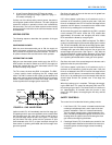
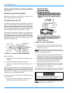
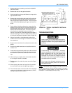
BURNER AIR SHUTTER ADJUSTMENT
Adjust burner shutters so no yellow flame is observed in the
heat exchanger tubes. Refer to Figure 17.
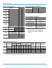
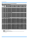
CHECKING SUPPLY AIR CFM
The RPM of the supply air blower will depend on the required
CFM, the unit accessories or options and the static resis-
tances of both the supply and the return air duct systems.
With this information, the RPM for the supply air blower and
the motor pulley adjustment (turns open) can be determined
from the blower performance data in Tables 11 and 12.
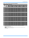
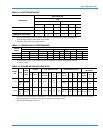
High speed drive accessories (containing a smaller blower
pulley and a shorter belt) are available for applications requir-
ing the supply air blower to produce higher CFM's and/or
higher static pressures. Use Model 1LD0416 for 15 ton units
and Model 1LD0417 for 20 ton units. Refer to Table 15 for
blower motor and drive data.
Note the following:
1. The supply air CFM must be within the limitations shown
in Table 2.
2. Pulleyscanbeadjustedinhalfturnincrements.
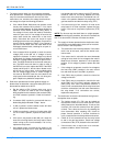
3. The tension on the belt should be adjusted as shown in
Figure 19.
Start the supply air blower motor. Adjust the resistances in
both the supply and the return air duct systems to balance
the air distribution throughout the conditioned space. The job
specifications may require that this balancing be done by
someone other than the equipment installer.
To check the supply air CFM after the initial balancing has
been completed:
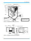
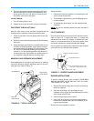
1. Remove the two 5/16" dot plugs from the blower motor
and the filter access panels shown in Figure 10.
2. Insert at least 8" of 1/4 inch tubing into each of these
holes for sufficient penetration into the air flow on both
sides of the indoor coil.
NOTE:
The tubes must be inserted and held in a position per-
pendicular to the air flow so that velocity pressure will not
affect the static pressure readings.
3. Using an inclined manometer, determine the pressure
drop across a dry evaporator coil. Since the moisture on
an evaporator coil may vary greatly, measuring the pres-
sure drop across a wet coil under field conditions would
be inaccurate. To assure a dry coil, the compressors
should be deactivated while the test is being run.
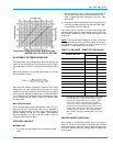
4. Knowing the pressure drop across a dry coil, the actual
CFM through the unit and clean 2" filters, can be deter-
mined from the curve in Figure 20.
After readings have been obtained, remove the tubes and
reinstall the two 5/16" dot plugs that were removed in Step 1.
NOTE:
De-energize the compressors before taking any test
measurements to assure a dry indoor coil.
FIGURE 18 : TYPICAL FLAME APPEARANCE
FIGURE 19 : BELT ADJUSTMENT
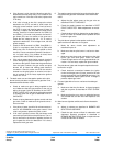
Failure to properly adjust the total system air quan-
tity can result in extensive blower damage.