


20
Initial Installation
QUALIFIED INSTALLERS ONLY
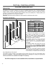
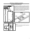
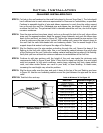
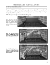
Step 3. To install the Round
Support Box/Wall Thimble
in a at ceiling, cut a 10
inch (25.4 cm) square hole
in the ceiling, centered in
the hole drilled in Step 2.
Frame the hole as shown
in Figure 21.
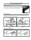
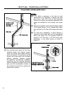
Step 4. Assemble the desired
lengths of black pipe
and elbows necessary to
reach from the appliance
adapter up through the
Round Support Box.
Insure that all pipe and
elbow connections are
in their fully twist-locked
position.
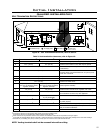
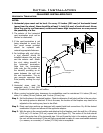
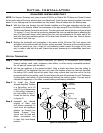
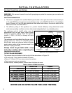
Figure 26. Vertical Vent Termination
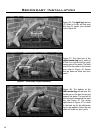
NOTE: For Simpson Duravent only, place a bead of Mil-Pac or Rutland No 78 Stove and Gasket Cement
on the outer edge of the inner exhaust pipe (non-ared end). Push the pipe sections together, then twist
about turn, making sure the two sections are fully locked. Wrap all seams with foil ducting tape.
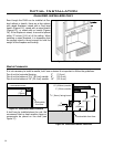
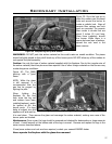
Step 4. With the hole now framed, the wall thimble installed, and the pipe extending into the wall,
proceed to the outside. Attach the termination to the pipe using RTV and Mil-Pac or Rutland No
78 Stove and Gasket Cement to seal joints. The vent pipe must extend into the vent cap at least
1 inches (3.2 cm). Secure the connection between the vent cap and the pipe by attaching the
two (2) sheet metal straps, which extend from the vent cap assembly to the outer wall of the
vent pipe. Bend any remaining portion of the strap back towards the vent cap. Security Secure
Vent uses a twist lock cap.
Step 5. Position the horizontal vent termination in the center of the 10 inches (25.4 cm) square hole
and attach to the exterior wall with the four screws provided. The arrow on the vent termination
should be pointing up. Run a bead of non-hardening mastic around the edges of the vent
cap, to make a seal with the wall. Ensure the proper clearances to combustibles have been
maintained.
VERTICAL TERMINATION:
Step 1. Check the instructions for required clearances (air spaces) to combustibles when passing
through ceilings, walls, roofs, enclosures, attic rafters, or other nearby combustible surfaces.
Do not pack air spaces with insulation.
Step 2. Set the gas appliance in the desired location. Drop a plumb bob down from the ceiling to
the position of the appliance ue exit, and mark the location where the vent will penetrate
the ceiling. Drill a small hole at this point. Next, drop a plumb bob from the roof to the hole
previously drilled in the ceiling, mark the spot where the vent will penetrate the roof. Determine
if ceiling joists, roof rafters, or other framing will obstruct the venting system. You may wish to
relocate the appliance, or to offset, to avoid cutting load bearing members.
Vertical
Termination
Storm Collar
Flashing
Roofing nails
Elbow Strap