


Initial Installation
QUALIFIED INSTALLERS ONLY
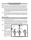
INSTALLATION OF ELECTRICAL WIRING FOR THE OPTIONAL FAN KIT:
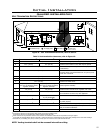
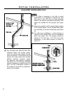
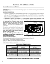
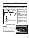
Figure 31. Wiring Diagram For Gas Valve.
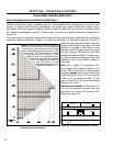
C
O
O
L
/
H
E
A
T
P
R
O
G
R
A
M
D
O
W
N
U
P
7
0
°
F
7
0
°
F
O
N
O
F
F
Optional
Remote
Control
ON/OFF/Remote
Thermostat Switch
Purple
Thermocouple
Blue
Thermopile
Grey
Inlet
Pressure
Tap
Gas Control
Valve
Manifold
Pressure Tap
Pilot Adjustment
Screw
Optional
Wall Switch
Optional
Thermostat
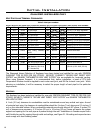
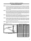
Wire Size Max. Length
14 gauge 100 ft (30.48 m)
16 gauge 60 ft (18.29 m)
18 gauge 40 ft (12.00 m)
20 gauge 25 ft (7.62 m)
22 gauge 18 ft (5.49 m)
Table 5. Recommended Thermostat
Wire Size.
23
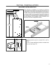
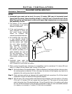
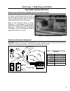
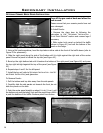
Figure 30. Install Electrical Outlet Into DV36.
The electric box/outlet must be hard wired to
the bottom left (or right if the gas line is to
come in on the left) of the unit if you plan to
install the Optional Fan Kit in the future.
Refer to local electrical bylaw for proper
installation. In the absence of local codes,
with the current CSA C22.1 Canadian Electrical
Code Part 1, Safety Standards For Electrical
Installations, or The Current National Electrical
Code ANSI / NFPA 70 in the US.
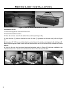
ELECTRICAL SYSTEM FOR THERMOSTAT:
CAUTION: Label all wires prior to disconnection when servicing controls. Wiring errors can cause
improper and dangerous operation. Verify proper operation after servicing.