


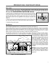
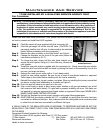
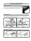
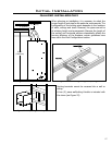

Mount the two framing mount brackets on each side and secure the replace
to framing with screws or nails (refer to Figure 7). The brackets will allow
for a ” (13 mm), ” (16 mm), ” (19 mm) thick nishing wall. The wall
may be nished up to the replace facing with combustible material.
Figure 11. Nail Tab.
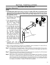
Initial Installation
QUALIFIED INSTALLERS ONLY
FRAMING MOUNT BRACKETS:
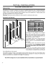
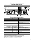
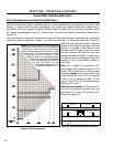
CORNER INSTALLATION:
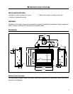
The dimensions for installing a replace in the corner of a room are given in Figures 12 and 13. Refer to
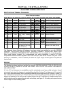
“INITIAL INSTALLATION - VENT CONFIGURATIONS AND RESTRICTOR SETTINGS” for allowable pipe lengths.
Do not interfere with the structural integrity of the walls.
OutsideWall
(Thick)
Inside
Wall
23
7
/
8
”
(605mm)
5
5
/
8
”
(143mm)
36
1
/
4
”
(920mm)
47
5
/
8
”
(1210mm)
33
3
/
4
”
(856mm)
15
1
/
2
”
(393mm)
11”
(279mm)
Figure 12. Dimensions for a corner installation, rear
vented.
13
Figure 13. Dimensions for a corner installation, top
vented.
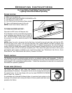
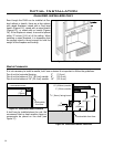
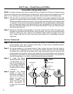
RAISED FIREPLACES AND HEARTHS:
Figure 15. Raised Fireplace with Floor Level Hearth
Figure 14. Raised Fireplace with Raised Hearth