


Page 8 R-3450
Stone Inlay Replacement of Standard Grille Top
Whenever the standard grille top is replaced with a stone inlay you must
install the top shield and heat shield, which are provided with the stone
inlay.
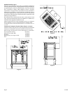
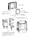
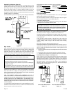
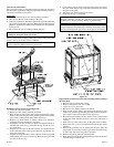
Installation of Optional Stone Inlay
1. Remove left grille, center grille and right grille from casing top.
2. Remove casing top from outer casing.
3. Place the casing top on a non-abrasive surface in order to protect the
porcelain finish. The exterior of the casing top should be facing the
non-abrasive surface.
4. Attach 11 5/8" x 11 5/8" top shield to the interior of the casing top
with (1) 3/8" bolt provided in hardware package.
5. Remove the (2) 1/2" hex-head screws located on the front of the heat
exchanger top. The screws are 8 3/4" apart. Do not remove the center
hex-head screw. Remove the (2) screw hole, knockouts located on
the back of the heat exchanger top. The knockouts are 8 3/4" apart.
Position the angled front on the 12" x 19 3/8" heat shield with the
front of the appliance. Align the (4) tabs with clearance holes on the
12" x 19 3/8" heat shield with the (4) screw holes on the heat
exchanger top. Attach the 12" x 19 3/8" heat shield to the heat
exchanger top with (2) 1/2" hex-head screws removed in Step 5 and
(2) 1/2" hex-head screws provided in hardware package.
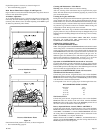
6. Place the casing top onto the outer casing. The casing top nests into
the outer casing.
7. Insert center stone inlay, left stone inlay and right stone inlay into
casing top.
8. Installation of stone inlay is completed.
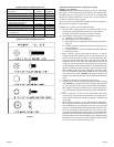
Parts List
Part Part Quantity
Description Number Supplied
11 5/8" x 11 5/8" Top Shield CI-091 1
12" x 19 3/8" Heat Shield CI-092 1
3/8" Bolt R-3646 1
1/2" Hex-Head Screw R-2737 4
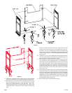
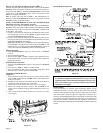
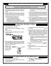
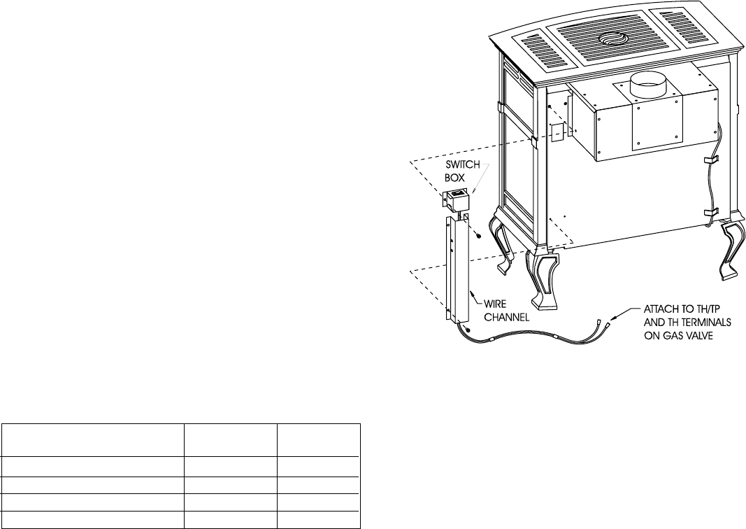
Installation of Wire Channel Assembly (Figure 10)
The ON/OFF/REMOTE switch with harness is factory installed into the
switch box.
After the appliance housing is installed into the cast iron outer casing the
wire channel can be installed.
1. Attach switch box on the left side of casing back with (2) 10 x 1/2"
provided screws.
2. Route wires from ON/OFF/REMOTE switch within wire channel.
3. Attach wire channel on the left side of the casing back with (4) 10
x 1/2" provided screws.
4. Attach the black and green (wires) female push-ons to the TH/TP
and TH (two outside male tabs) terminals on gas valve.
5. Identify vent safety switch wire harness. The first wire is installed
into magnet section on gas valve. The second wire is attached to the
TH/TP terminal on gas valve. Route opposite end of vent safety
switch wire harness within (2) metal clips on exterior of rear cover.
Attach (2) 1/4" female push-ons on vent safety switch wire harness
onto (2) 1/4" male tabs on vent safety switch which is located on the
side of draft diverter.
Figure 10
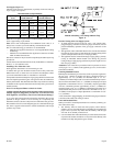
Venting
1. Flue pipe must be as large as the flue collar on the draft diverter.
2. Maintain an upward slope of at least 1/4 inch (6mm) per foot of
horizontal run.
3. Run flue pipe as directly as possible with a minimum of elbows.
4. Flue pipe should extend through the wall of a chimney to be flush
with inner wall.
5. Flue pipe must be adequately supported by metal straps.
6. Single wall vent pipe may be attached directly to the draft hood of
the fireplace heater when a clearance of 2 1/2 inches (64mm) is
maintained between the single wall vent pipe and the combustible
wall of the room in which the fireplace heater is located. Use double
wall vent pipe for clearances less than 2 1/2 inches (64mm) to
combustibles.
7. For flue pipe running through walls and roof, use B-1 [1 inch (25mm)
clearance to combustibles] vent pipe.
8. Chimneys should extend at least 2 feet (.6m) above the roof and
above any object or nearby building within 10 feet (3m).
9. Open tees should not be used in the flue pipe.
10. Appliance must not be connected to a chimney flue that is servicing
a separate solid-fuel burning appliance.
For proper venting, do not attach a 90° elbow directly to draft diverter. If
possible, attach 2 feet (.6m) of straight vent pipe before an elbow is used.
Use of 45° elbows is recommended.
Uninsulated single-wall metal pipe shall not be used outdoors in cold
climates for venting gas utilization equipment.
Ventilation and Combustion Air
Fireplace heaters shall be installed in a location in which the facilities for
ventilation permit satisfactory combustion of gas and proper venting
under normal conditions. In buildings of conventional frame, brick or
stone construction without tight storm windows and doors, infiltration is
normally adequate to provide for combustion and draft hood dilution.
Where appliances are installed in a confined space within a building, the
building being of unusually tight construction, air for combustion and
ventilation must be obtained directly from outdoors or from such spaces
that freely communicate with the outdoors. Under these conditions, the
confined space shall be provided with two permanent openings, one near
the top of the enclosure and one near the bottom; each opening shall have
a free area of not less than one square inch (6.5cm
2
) per 1,000 BTU's
(.3KW) of total input. The draft hood must be in the same atmospheric
pressure zone as the combustion air inlet to the appliance and shall be so
located so that the relief opening is accessible for checking vent operation.